Photoelectric oscillator

An optoelectronic oscillator and optoelectronic hybrid technology, applied in the field of lasers, can solve the problems of insufficient narrow-band optical filtering performance and too wide passband bandwidth.

Active Publication Date: 2015-12-30
BEIJING UNIV OF POSTS & TELECOMM
View PDF5 Cites 12 Cited by
  • Summary
  • Abstract
  • Description
  • Claims
  • Application Information

AI Technical Summary

Problems solved by technology

[0008] The purpose of the present invention is to solve the technical defect that the passband bandwidth of the traditional optical filt

Method used


Image

  • Photoelectric oscillator
  • Photoelectric oscillator
  • Photoelectric oscillator

Examples


Embodiment Construction

[0039] In order to make the object, technical solution and advantages of the present invention clearer, the embodiments of the present invention will be further described in detail below in conjunction with the accompanying drawings.

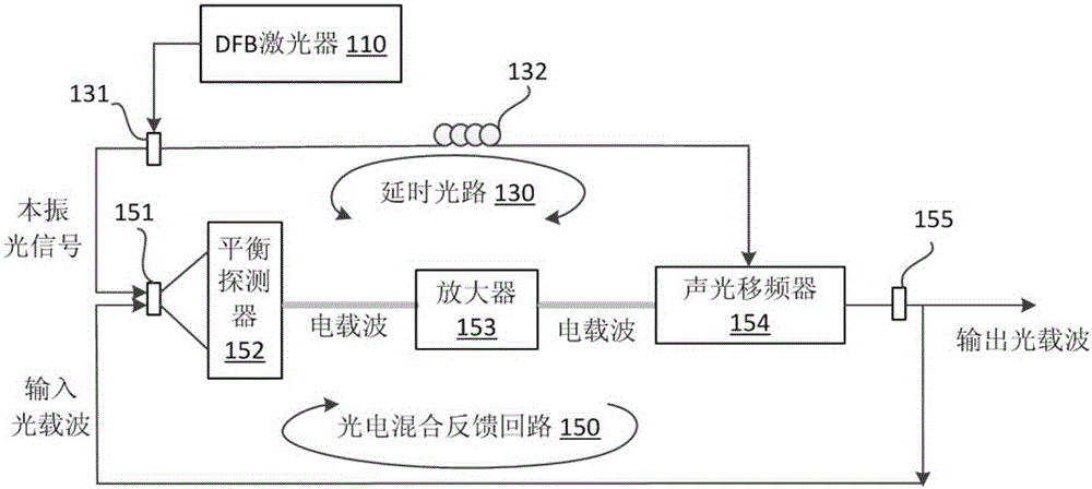
[0040] This embodiment provides an optical-electrical hybrid oscillator, in which an ultra-narrow-bandwidth optical filter with fixed time delay and bandwidth is inserted into a short optical fiber cavity. According to the Kramers-Kronig relationship, such ultra-narrowband filtering is always accompanied by a long time delay (the so-called slow light filter). This not only avoids the instability caused by long optical fibers, but also provides long delay, and then uses ultra-narrowband filtering to achieve the purpose of single longitudinal mode and narrow line width at the same time. However, it is very difficult to directly implement MHz-level filtering on such a high-frequency optical carrier (the frequency of the 1550nm communication band is...


PUM


Abstract

The invention provides a photoelectric oscillator which comprises a DFB laser device, a delay optical path and a photoelectric mixing feedback loop. The DFB laser device is used for generating local oscillator optical signals. The delay optical path is used for delaying the local oscillator optical signals. The photoelectric mixing feedback loop is used for carrying out down-converting processing on the local oscillator signals and input optical carrier waves to obtain low-frequency electrical carrier waves, filtering the electrical carrier waves in a narrow-band mode, carrying out up-converting processing on the delayed local oscillator optical signals and the filtered electric carrier waves, and outputting optical carrier waves. Optical delay generated by the delay optical path and electrical delay generated by the photoelectric mixing feedback loop are matched so as to eliminate phase noise attached to the local oscillator signals on the output optical carrier waves. The method of electrical assistance is utilized, a Q value up to 1.4*10<7> is achieved equivalently, intracavity delay and gain are provided by an electric device, and sensitivity to environment factors caused by long optical fibers and loud noise caused by an optical amplifier are avoided.

Description

technical field [0001] The invention relates to the technical field of lasers, in particular to a photoelectric oscillator for generating single longitudinal mode and ultra-narrow linewidth laser. Background technique [0002] Single longitudinal mode, narrow linewidth lasers are extremely important in many applications, such as fiber optic sensing, fiber optic communication, and microwave frequency generation. The so-called single longitudinal mode means that the output light exhibits a single-frequency characteristic in the frequency domain, which is very important when the light needs to be modulated. Because the longitudinal mode spacing of general multi-longitudinal mode lasers is relatively narrow, when it is modulated (especially high-speed digital modulation), multiple longitudinal modes will be modulated at the same time, resulting in spectral overlap, which will increase the bit error rate of the system. In addition, in the field of analog modulation that is sensi...

Claims


Application Information

Patent Timeline
IPC IPC(8): H01S1/02
Inventor 戴一堂张梓平尹飞飞周月李建强徐坤
Owner BEIJING UNIV OF POSTS & TELECOMM
Why Eureka
Try Eureka