

Slitting mill
A technology of hob cutting machine and cutting knife, applied in shearing device, shearing machine equipment, metal processing equipment and other directions, can solve the problems of large floor space, troublesome assembly and debugging, etc., achieve small floor space and good product quality , the effect of large size
- Summary
- Abstract
- Description
- Claims
- Application Information
AI Technical Summary
Problems solved by technology
Method used
Image

Examples
Embodiment
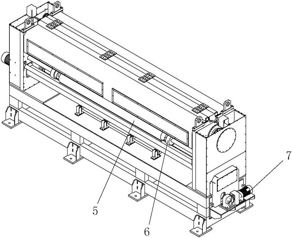
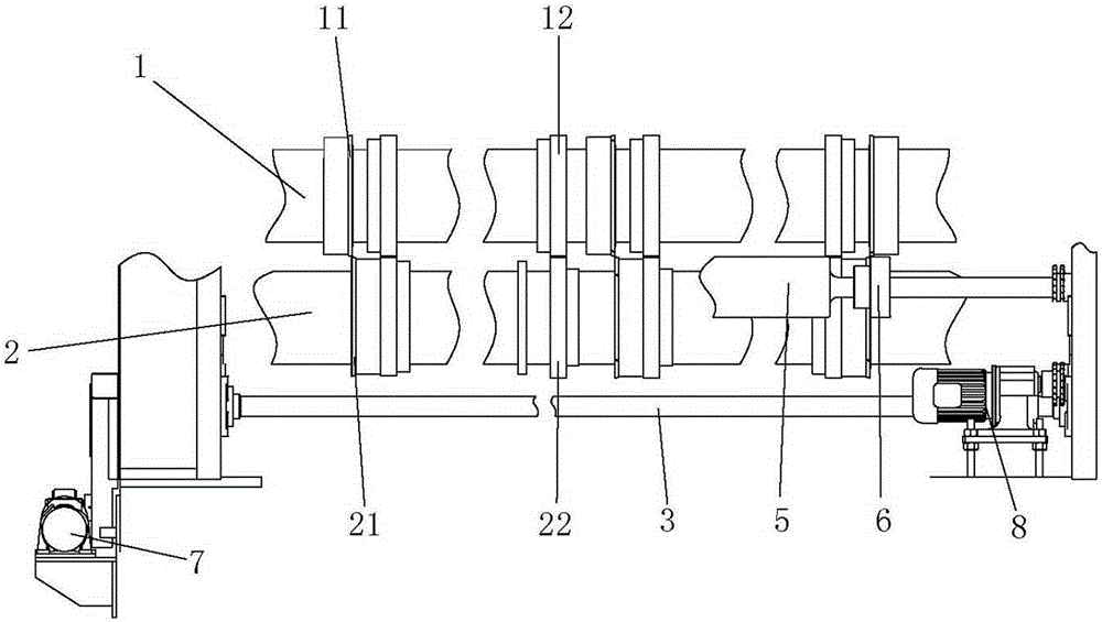
[0029] Example: such as figure 1 with figure 2 As shown, a hobbing machine includes an upper roll 1, a lower roll 2, a main shaft 3, an input roll 4 and an output roll 5. Upper roll 1 is provided with three upper ring knives 11 that rotate with upper roll 1, and lower roll 2 is provided with three lower ring knives 21 that rotate with lower roll 2. Each upper ring knife 11 and Corresponding to it, the cutting edge of the lower ring knife 21 is opposite to form a cutting knife group. The hobbing machine is provided with three groups of cutting knife groups, wherein two groups are arranged at the two ends of the upper roller 1 and the lower roller 2, and the other group is arranged at the middle of the upper roller 1 and the lower roller 2.
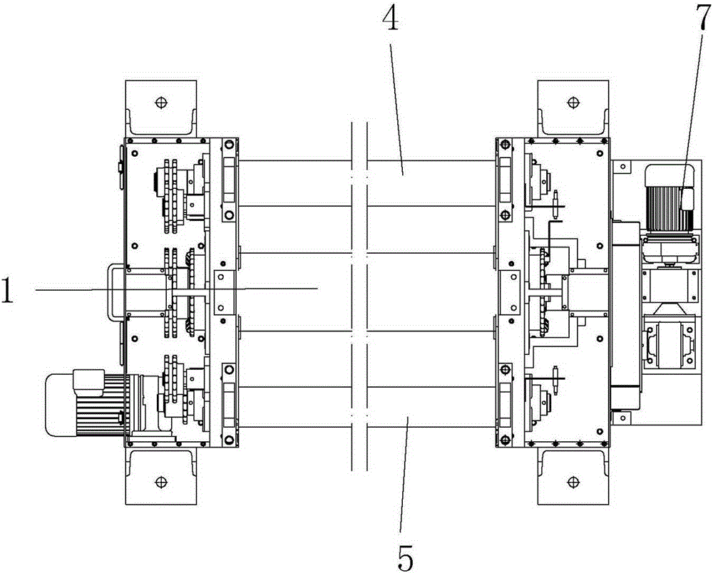
[0030] Such as Figure 4 As shown, both the upper roll 1 and the lower roll 2 are actively rotating rolls, both ends of the upper roll 1 are installed through eccentric bushings, and the left and right ends maintain the same eccentric d...
PUM
 Abstract
Description
Claims
Application Information