Automatic control device for floating winding type plastic cloth of salt pond

An automatic control device and control device technology, applied in hoisting devices, clockwork mechanisms, etc., can solve the problem of reducing the service life of plastic sheets (plastic tarpaulins), the inability to simultaneously retract and deploy multiple salt pools, and the difficulty in realizing deployment and traction Synchronization and other issues to achieve the effect of improving reliability and safety, small changes, and increasing service life

Inactive Publication Date: 2016-01-06
TIANJIN BOYADA TECH +1
View PDF5 Cites 4 Cited by
  • Summary
  • Abstract
  • Description
  • Claims
  • Application Information

AI Technical Summary

Problems solved by technology

[0002] At present, the salt pond plastic thatch system used in the salt field basically does not have automatic control functions. The operation of the equipment is completely operated by the operator manually or by remote control. Both motors run at a power frequency of 50Hz, and their angular velocity is constant. As the unwinding proceeds, the diameter of the outer edge of the plastic cloth wound on the floating reel gradually decreases. At the same time, the traction rope wound on the reel Instead, the diameter of the outer edge gradually increases. Therefore, in manual operation, the two motors must be started and stopped, and the unwinding speed must be coordinated through manual intervention.
Therefore, there are serious defects and deficiencies in the existing control methods, that is, it is difficult to realize the real synchronization of deployment and traction during operation, and the plastic cloth (plastic tarpaulin) often appears too loose and too tight.
When it is too loose, the plastic cloth (plastic tarpaulin) will roll back at the holding roller, causing tearing of the cloth; The service life of the cloth (plastic thatch cloth), if the tension is too large, the large rope may break and the floating reel may be pulled out from the holding roller and broken.
In addition, each salt pond requires at least 2-3 operators
Simultaneous deployment of multiple salt pools cannot be realized

Method used


Image

  • Automatic control device for floating winding type plastic cloth of salt pond
  • Automatic control device for floating winding type plastic cloth of salt pond

Examples


Embodiment Construction

[0023] The present invention will be further described in detail below through the specific examples, the following examples are only descriptive, not restrictive, and cannot limit the protection scope of the present invention with this.

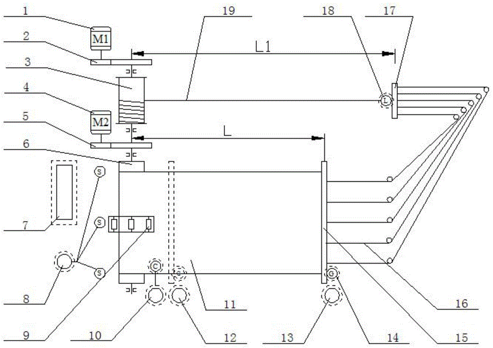
[0024] An automatic control device for floating roll-type plastic thatch in a salt pond, which includes a plastic thatch 11, a floating reel 6, a floating reel motor 4, a floating reel reduction box 5, a traction floating plate 15, a floating plate traction rope, a reel 3, and a reel deceleration Box 2, reel motor 1 and control unit; one end of the plastic thatch 11 is wound on the floating reel 6, the floating reel 6 is driven by the floating reel motor 4 and the floating reel reduction box 5, and the other end of the plastic thatch 11 is fixed on the traction buoy On the plate 15, the traction floating plate 15 is connected and wound on the reel 3 through the traction rope of the floating plate, and the reel 3 is driven by the reel motor 1 ...


PUM


Abstract

Th invention relates to an automatic control device for a floating winding type plastic cloth of a salt pond. The automatic control device is characterized in that the automatic control device comprises the plastic cloth, a floating winding shaft, a floating winding shaft motor, a floating winding shaft reduction gearbox, a traction floating plate, a floating plate traction rope, a winding drum, a winding drum reduction gearbox, a winding drum motor and a control device body; one end of the plastic cloth is wound around the floating winding shaft; the floating winding shaft is driven by the floating winding shaft motor and the floating winding shaft reduction gearbox; the other end of the plastic cloth is fixed to the traction floating plate; the traction floating plate is connected with the winding drum through the floating plate traction rope in a wound mode; the winding drum is driven by the winding drum motor and the winding drum reduction gearbox; the floating winding shaft motor and the winding drum motor are controlled by the control device body synchronously. The automatic control device is scientific and reasonable in design. The key technical problem of automatic control over a plastic cloth system of the salt pond is solved. Automatic cooperative control over the whole process of spreading and traction of the plastic cloth in the floating winding type plastic cloth system is achieved.

Description

technical field [0001] The invention relates to plastic thatch equipment for a crystallization pool in a salt field, in particular to an automatic control device for a floating roll type plastic thatch in a salt pond. Background technique [0002] At present, the salt pond plastic thatch system used in the salt field basically does not have automatic control functions. The operation of the equipment is completely operated by the operator manually or by remote control. Both motors run at a power frequency of 50Hz, and their angular velocity is constant. As the unwinding proceeds, the diameter of the outer edge of the plastic cloth wound on the floating reel gradually decreases. At the same time, the traction rope wound on the reel On the contrary, the diameter of the outer edge of the machine gradually increases. Therefore, in manual operation, the two motors must be started and stopped, and the unwinding speed must be coordinated through manual intervention. Therefore exist...

Claims


Application Information

Patent Timeline
Patent Type & Authority Applications(China)
IPC IPC(8): B66D1/12B66D1/48B66D1/14
Inventor 范树礼张德强
Owner TIANJIN BOYADA TECH
Why Eureka
Try Eureka