Composite heat-insulation and sound-insulation plate

A technology of composite thermal insulation and sound insulation panels, applied in thermal insulation, sound insulation, building components, etc., can solve problems such as unsuitable for application

Active Publication Date: 2016-01-06
NANJING BREADY ELECTRONICS CO LTD
View PDF6 Cites 6 Cited by
  • Summary
  • Abstract
  • Description
  • Claims
  • Application Information

AI Technical Summary

Problems solved by technology

[0004] Based on this, it is necessary to provide a composite thermal insulation and sound insulation board that is suitable for application and can reduce noise in view of the problems that traditional building insulation and sound insulation materials have various disadvantages and are not suitable for application.

Method used


Image

  • Composite heat-insulation and sound-insulation plate
  • Composite heat-insulation and sound-insulation plate
  • Composite heat-insulation and sound-insulation plate

Examples


Embodiment 1

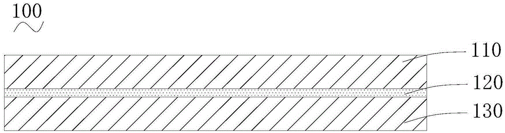
[0051] The composite thermal insulation board 100 of this embodiment is such as figure 2 As shown, it includes a first layer 110, a polyurea aerogel layer 120, and a second layer 130 stacked in sequence. The above three layers are bonded together in sequence. The first layer 110 and the second layer 130 are both paper-faced gypsum layers. The thicknesses of the first layer 110, the polyurea aerogel layer 120, and the second layer 130 are 12 mm, 5 mm, and 12 mm, respectively. The density of the polyurea aerogel layer 120 is 15kg / cm 3 . The size of the composite heat insulation and sound insulation board 100 of this embodiment is 1.2 m×2.4 m.

Embodiment 2

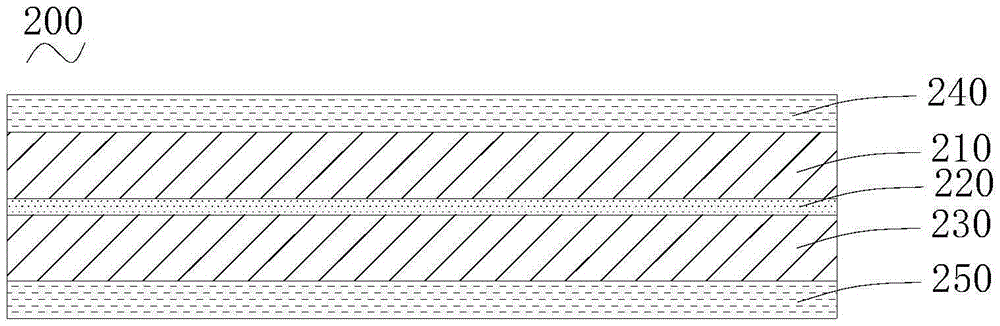
[0053] The composite heat insulation and sound insulation board 200 of this embodiment is such as image 3 As shown, in addition to the first layer 210, the polyurea aerogel layer 220, and the second layer 230 stacked in sequence, it also includes a first fireproof layer 240 located outside the first layer 210 and a second layer 230 outside. The second fire protection layer 250. The above five layers are glued together in sequence. The first layer 210 and the second layer 230 are both paper-faced gypsum layers. The thickness of the first layer 210, the polyurea aerogel layer 220, and the second layer 230 are 12 mm, 2 mm, and 12 mm, respectively. The thickness of the first fireproof layer 240 and the second fireproof layer 250 are both 5 mm. The density of the polyurea aerogel layer 220 is 15kg / cm 3 . The size of the composite heat insulation and sound insulation board 200 of this embodiment is 1.2m×2.4m.

Embodiment 3

[0055] The difference between this embodiment and Embodiment 2 is that the composite heat and sound insulation board does not include a second fireproof layer. When used as a building board and implemented specifically, the first fireproof layer is placed on the side far away from the wall, and the second layer is placed on the side close to the wall and in contact with the surface of the wall.


PUM

PropertyMeasurementUnit
thicknessaaaaaaaaaa
thicknessaaaaaaaaaa
densityaaaaaaaaaa

Abstract

The invention discloses a composite heat-insulation and sound-insulation plate. The composite heat-insulation and sound-insulation plate comprises a first layer, a polyurea aerogel layer and a second layer which are stacked sequentially, wherein a first sound attenuation interface which is used for attenuating sound is formed between the first layer and the polyurea aerogel layer; and a second sound attenuation interface which is used for attenuating sound is formed between the second layer and the polyurea aerogel layer. In a sound transmission process, sound is transmitted in a cross-medium mode for several times, and energy of the sound is consumed greatly. In the next place, a micro-nano-level porous structure assembled by polyurea nano fibers and nano particles in the polyurea aerogel layer of the composite heat-insulation and sound-insulation plate can effectively attenuate energy of sound waves, and effects of insulating sound and reducing noises are achieved. Moreover, because the polyurea aerogel layer is a porous material, an insulation function can be fulfilled. In addition, the size of the polyurea aerogel layer is large, and the polyurea aerogel layer can serve as a building board directly. Therefore, the composite heat-insulation and sound-insulation plate can serve as a building material, and heat-insulation and sound-insulation functions are fulfilled.

Description

Technical field [0001] The invention relates to the field of heat insulation and sound insulation materials, in particular to a composite heat insulation and sound insulation board. Background technique [0002] With the development of social industrialization, the surrounding environment where we live is filled with more and more noises, such as noise generated by construction projects and vehicles, noisy noise in crowded places, etc. These noises have caused a lot to our lives. Big impact. Therefore, the demand for sound insulation materials that can reduce these noises is increasing day by day. Although some materials have the function of sound insulation, they tend to reduce the insulation effect. [0003] Thermal insulation and sound insulation materials in construction mainly include the following categories: the first category is glass wool, rock wool, etc., these materials have disadvantages such as heavy weight, complex construction, serious environmental pollution, and ...

Claims


Application Information

Patent Timeline
Patent Type & Authority Applications(China)
IPC IPC(8): E04B1/90E04B1/94
Inventor 王芬陆群刘志成
Owner NANJING BREADY ELECTRONICS CO LTD
Why Eureka
Try Eureka