
wind power system

A technology of wind power generation system and generator, which is applied in the direction of wind power generator, wind power generator combination, wind power generator control, etc., can solve the problems of wind power generator installed power can only be increased, height is low, wind speed is low, etc., to achieve new The total amount of energy generation, the expansion of the site selection range, and the effect of low altitude

Active Publication Date: 2018-12-18
SOOAR BEIJING INVESTMENT MANAGEMENT GRP
View PDF4 Cites 0 Cited by
  • Summary
  • Abstract
  • Description
  • Claims
  • Application Information

AI Technical Summary

Problems solved by technology

The wind-solar complementary solar power generation system has the following problems: 1) The wind power generation device is set under the photovoltaic panel, the height is too low (usually, the wind speed increases with the increase of height), and the ground is uneven, so the wind energy will be blocked by obstacles, etc. 2) The wind energy will be reduced after passing through the photovoltaic panels, so there is basically no available wind energy; 3) If half of the wind power generation device is above the photovoltaic panels, then half of the wind power will The power generation device will block the photovoltaic panels, which may cause short-circuit burning of the covered photovoltaic panels; 4) The wind power generation device does not have the ability to face the wind at all times, and the effective utilization rate of wind energy is low
The frame-type horizontal wind generator has the following problems: 1) its wind rotor frame is located on the periphery of the blade, which does not enhance the strength of the blade itself, and too many frames on the periphery also interfere with the flow of air. It is not conducive to the effective use of wind energy; 2) because of its "the rotor shaft of the generator (9) with two ends of the shaft head is connected with the rotating shaft of the fan impeller group (8) through a coupling", in order to ensure that both sides When the wind blade receives the wind, the wind deflector is arranged at the lower edge of the blade, so that the wind blade rotating to the upwind side will be subject to greater resistance, resulting in a decrease in the effective torque output by the fan shaft
The omnidirectional rotating double wind turbine wind turbine has the following problems: 1) the blade shaft is a cantilever structure, which is not conducive to the formation of effective structural strength; 2) the geometric shape of the blades leads to low wind energy utilization efficiency and insufficient overall output
The wind-solar hybrid power generation device has the following problems: 1) Only when the wind blows from the side of the photovoltaic module, the fan can generate electricity, and the wind energy will be blocked by the photovoltaic module if the wind direction is slightly shifted; 2) The vertical axis generator is installed vertically When the horizontal length of the photovoltaic module cannot be fully utilized, the only way to increase the installed power of the wind turbine is to increase the diameter of its blades, which directly affects the installation area of ​​the entire device; 3) The wind speed at low altitudes is relatively low, and the device cannot Collecting and directing wind, resulting in low power generation efficiency and low power generation

Method used


Image

  • wind power system
  • wind power system
  • wind power system

Examples


Embodiment Construction

[0029] Features and exemplary embodiments of various aspects of the invention will be described in detail below. In the following detailed description, numerous specific details are set forth in order to provide a thorough understanding of the present invention. It will be apparent, however, to one skilled in the art that the present invention may be practiced without some of these specific details. The following description of the embodiments is only to provide a better understanding of the present invention by showing examples of the present invention. The present invention is by no means limited to any specific configurations and algorithms presented below, but covers any modification, substitution and improvement of elements, components and algorithms without departing from the spirit of the invention. In the drawings and the following description, well-known structures and techniques have not been shown in order to avoid unnecessarily obscuring the present invention.

...


PUM


Abstract

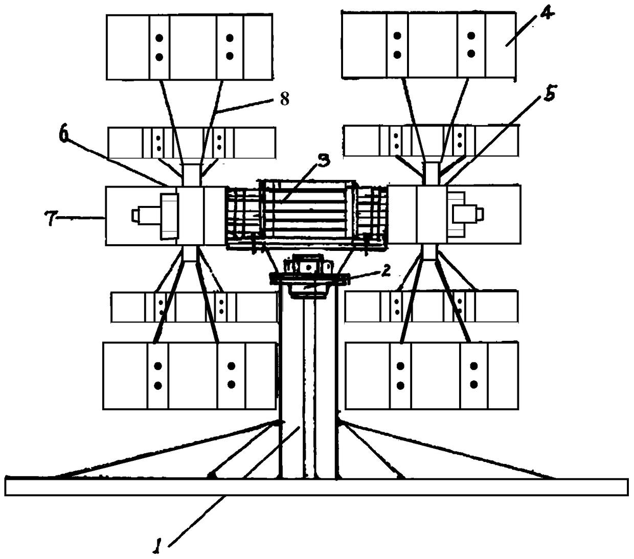
The invention provides a wind power generation system which comprises a generator, at least two sets of resistance type fans and a rotation type bearing device. The resistance type fans are adjacently and horizontally arranged on the rotation type bearing device in a front-back manner and drive the generator to cut a magnetic line so as to generate electric energy. According to the wind power generation system in the embodiment, wind power generation under the low-height and low-air-speed conditions is achieved by horizontally arranging the resistance type fans; the address selecting range of wind power generation is greatly expanded; the power generation link and the power utilization link can be drawn close to the maximum degree; and the wind power generation system can be organically combined with other new energy power generation schemes to improve the total power generation amount of new energy in unit area.

Description

technical field [0001] The invention relates to the field of wind power generation, in particular to a wind power generation system. Background technique [0002] In order to obtain stable and high-speed wind resources and reduce the cost of electricity, the current wind power generation is increasingly developing in the direction of tall towers and single-machine large-capacity. However, areas suitable for building such wind farms (for example, northern Xinjiang, Inner Mongolia, northern Gansu, etc.) are often far away from power consumption centers, which leads to a disconnect between power generation and power consumption. heavy burden. [0003] In the field of low wind speed power generation, permanent magnet generators are usually used to convert the mechanical energy of wind turbines into electrical energy, but limited by factors such as materials, technology and cost, the speed of permanent magnet generators is usually not lower than 75 revolutions per minute (rpm) ...

Claims


Application Information

Patent Timeline
Patent Type & Authority Patents(China)
IPC IPC(8): F03D9/25F03D3/06F03D7/06F03D17/00
CPCY02E10/74
Inventor 南寅王立昌耿存杰朱超
Owner SOOAR BEIJING INVESTMENT MANAGEMENT GRP
Learn More