Quantum dot laser pointing type backlight module and naked eye 3D display device

A technology of backlight modules and lasers, applied in light guides, optics, instruments, etc., can solve the problems of reduced image resolution, unfavorable industrial mass production, and difficult application, and achieve the effect of simplifying complexity

Inactive Publication Date: 2016-01-06
SVG TECH GRP CO LTD +1
View PDF11 Cites 38 Cited by
  • Summary
  • Abstract
  • Description
  • Claims
  • Application Information

AI Technical Summary

Problems solved by technology

At present, the light guide plate of the nano-diffraction grating is applied to the backlight module, but there are the following problems: For a nano-diffraction grating, no matter from the positive X direction or the negative X direction, the incident light will be diffracted and emitted. When the nano-diffraction grating is used as a pixel on a rectangular light guide plate, since the rectangular light guide plate has only two pairs of non-parallel opposite sides, the expression of color must rely on the matching of three colors of RGB (or other three colors), which means If 3-color light sources are used in a rectangular light guide plate, there must be a pair of light sources with two different colors appearing on the opposite sides. On the nano-diffraction grating, two colors of light are emitted from one pixel at the same time, thus forming a "mixed light"
The international patent WO2014 / 051624A1 discloses the use of integrated hybrid laser waveguide array directional backlight to realize multi-view display, using waveguide array to couple red, green and blue three-color light, and realizing directional export of light through pixel type grating, although this method Color 3D display can be realized, but due to the use of multi-waveguide arrays, the resolution of the obtained image is greatly reduced, and at the same time, the precision of the manufacturing process of the directional backlight structure is very high.
The waveguide structures used in the above patents are all hexagonal or triangular, which is difficult to combine with today’s mainstream display methods, especially difficult to apply to rectangular display methods like smartphones, which will not be conducive to industrial large-scale Production

Method used


Image

  • Quantum dot laser pointing type backlight module and naked eye 3D display device
  • Quantum dot laser pointing type backlight module and naked eye 3D display device
  • Quantum dot laser pointing type backlight module and naked eye 3D display device

Examples


no. 1 approach

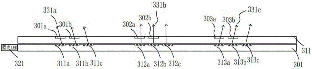
[0042] See image 3 , image 3 It is a structural schematic diagram of a pixelated quantum dot laser pointing type backlight module in the first embodiment of the present invention. It includes a first rectangular light guide plate 311 and a second rectangular light guide plate 301, and these two rectangular light guide plates are closely stacked together in actual use. The light-emitting side is defined as the light-emitting surface of the rectangular light guide plate. The light-emitting surface of each rectangular light guide plate is covered with pixels. Each pixel on the first rectangular light guide plate 311 represents a pixelated quantum dot laser structure. Each pixel on the two rectangular light guide plates 301 represents a nano-diffraction grating, and the quantum dot laser can emit red light and green light after being excited by blue light, and maintain the direction of the exciting light. by image 3 For example, in image 3 The figure simply shows a plurali...


PUM

PropertyMeasurementUnit
viewing angleaaaaaaaaaa
refractive indexaaaaaaaaaa

Abstract

The invention provides a quantum dot laser pointing type backlight module and naked eye 3D display device. The device comprises at least two rectangular light guide plates which are mutually tightly laminated. The light-exiting surface of each light guide plate comprises pixels of different nanometer grating orientations. Blue lights emitted by a light source group are collimated and come into the light guide plates. Groups of pixel arrays of the light-exiting surface of each light guide plate couple the lights in the light guide plate out of the surface of the light guide plate to form outgoing lights of different orientations. The outgoing lights irradiate red and green quantum dot pixel lasers corresponding to the surfaces of the light guide plates, so as to inspire red and green lights. Red, green and blue lights are in the same outgoing direction, so as to form a pointing type white light backlight source with different outgoing angles. The outgoing angles are corresponding to multi-angle images of a liquid crystal display LCD, so that color 3D display is formed and can be observed through naked eyes.

Description

technical field [0001] The invention relates to the field of flat-panel naked-eye 3D display, in particular to a directional backlight module and a naked-eye 3D display device based on the backlight module. Background technique [0002] With the improvement of people's living standards, flat 2D display has become more and more difficult to meet people's needs, and people began to pursue 3D display with a sense of depth, so that they can feel the reality of the existence of objects more clearly. Since Wheatstone first proposed the use of stereoscopic mirrors to realize 3D display in 1838, after more than a century of development, the research on 3D display has been in full swing, and various ways to realize 3D display have been proposed successively. [0003] Naked-eye 3D display technology does not need to wear any visual aids (such as eyes, helmets, etc.) when watching. At present, more mature naked-eye 3D display technologies include parallax barriers and cylindrical lens ...

Claims


Application Information

Patent Timeline
Patent Type & Authority Applications(China)
IPC IPC(8): G02B6/00G02F1/13357G02B27/22
CPCG02B6/0023G02B6/0025G02B6/0033G02B6/0045G02B6/0076G02F1/1336G02B30/34G02F1/133614G02B6/0036
Inventor 陈林森万文强乔文黄文彬楼益民朱鸣罗明辉
Owner SVG TECH GRP CO LTD
Why Eureka
Try Eureka