High-safety fuel rod and manufacturing method thereof

A technology with high safety and manufacturing methods, which is applied in the field of nuclear power, can solve the problems of soft matrix, broken fuel particles, and bending of integrated fuel rods, so as to reduce the possibility of broken, reduce the release of hydrogen, and slow down corrosion The effect of the reaction

Active Publication Date: 2017-10-17
CHINA NUCLEAR POWER TECH RES INST CO LTD +2
View PDF3 Cites 0 Cited by
  • Summary
  • Abstract
  • Description
  • Claims
  • Application Information

AI Technical Summary

Problems solved by technology

[0006] 1. For the above-mentioned structural scheme, if the external force on the fuel rod is relatively large during the operating state of the reactor or other non-operating states (such as manufacturing, transportation, etc.), the external force is easily transmitted to the coating fuel particles through the zirconium alloy matrix, If the external force reaches a certain limit, it will cause the fragmentation of fuel particles, thereby affecting the safe operation of the reactor;
[0007] 2. The matrix material of the above structural scheme is zirconium alloy. In the event of a serious reactor accident, the zirconium alloy matrix will react with water at high temperature and release a large amount of hydrogen, seriously affecting the safety of the reactor;
[0008] 3. During the processing of the above structural scheme, in consideration of maintaining the completeness of the fuel particles, forging and other high-pressure processing methods must not be used, which will inevitably cause the matrix to be soft, resulting in a relatively small rigidity of the entire integrated fuel rod. When running in the reactor, it is easy to cause the bending of the integrated fuel rod, thus affecting the safety of the reactor operation;
[0009] 4. Considering that there are also fuel particles distributed around the periphery of the above structural scheme, resulting in poor processability, the size of the integrated fuel rod cannot be accurately controlled

Method used


Image

  • High-safety fuel rod and manufacturing method thereof
  • High-safety fuel rod and manufacturing method thereof
  • High-safety fuel rod and manufacturing method thereof

Examples


Embodiment Construction

[0035] In order to have a clearer understanding of the technical features, purposes and effects of the present invention, the specific implementation manners of the present invention will now be described in detail with reference to the accompanying drawings.

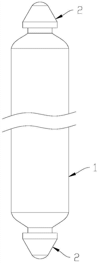
[0036] Such as figure 1 and figure 2 As shown, the high-safety fuel rod in a preferred embodiment of the present invention includes a rod body 1 and two end plugs 2 arranged at the longitudinal ends of the rod body 1, the end plugs 2 are fixedly connected with the rod body 1, and the end caps 2 connect the rod body The end faces of the body 1 are covered. The end plug 2 can facilitate operations such as assembly and maintenance of the fuel rod in the later stage. The end plug 2 can also be replaced with other components for operations such as assembling.

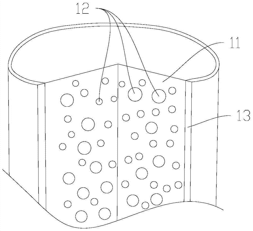
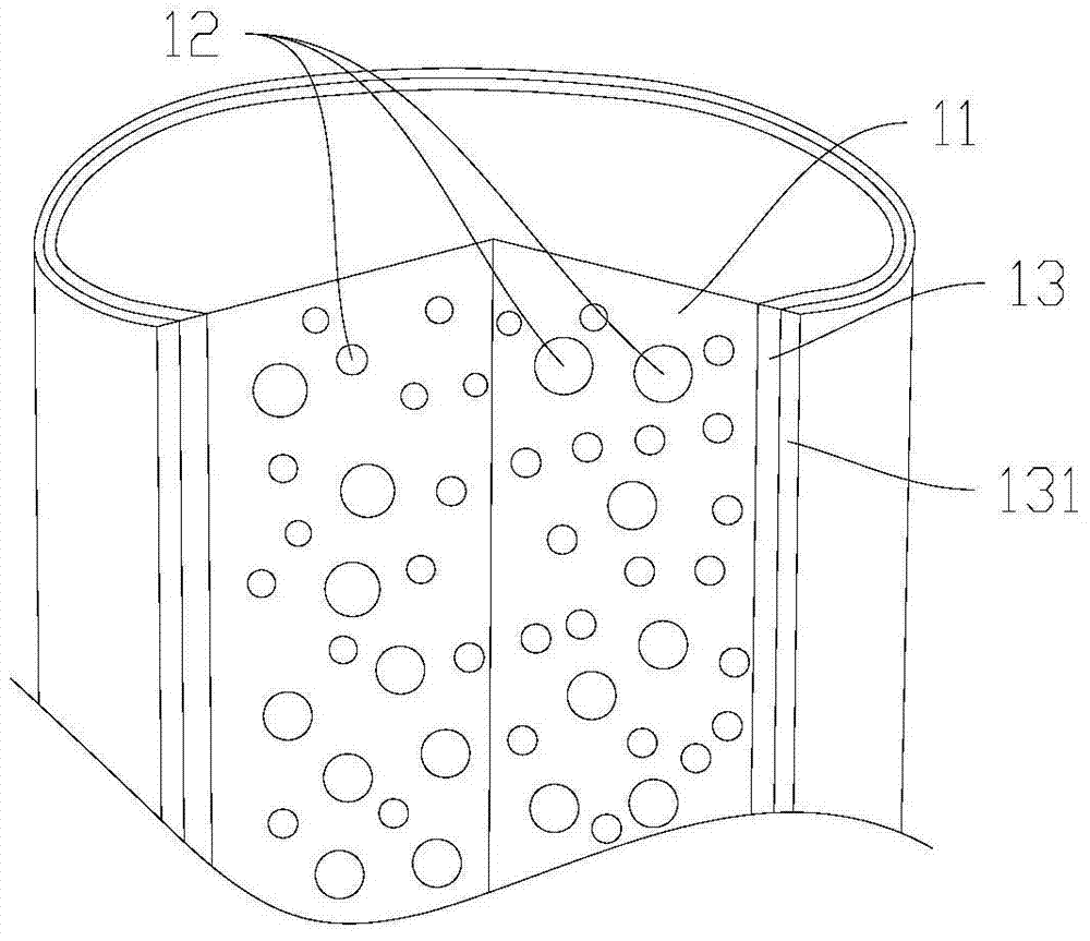
[0037] The rod body 1 includes a rod-shaped metal matrix 11 and fuel particles 12 dispersed in the metal matrix 11 . Further, the rod body 1 also includes a fue...


PUM

PropertyMeasurementUnit
thicknessaaaaaaaaaa

Abstract

The invention relates to a high-safety fuel rod. The high-safety fuel rod comprises a rod body which comprises a rod-like metal substrate, fuel particles dispersed in the metal substrate and a fuel-free layer, wherein the periphery of the metal substrate is coated with the fuel-free layer, and the hardness of the fuel-free layer is higher than that of the metal substrate. The preparation method of the rod body comprises the following steps that A, the fuel particles are mixed with metal substrate powder, and a substrate green blank is prepared; B, the periphery of the substrate green blank is coated with a certain thickness of hard powder which forms a rod body green blank with the substrate green blank; C, the rod body green blank is sintered, and the rod body is formed. According to the high-safety fuel rod, a fuel-free area with high hardness is arranged on the periphery, the strength of the fuel rod is improved, machining is convenient, the size is convenient to control, the corrosion reaction is alleviated, release of hydrogen is reduced, and the safety is improved.

Description

technical field [0001] The invention relates to the technical field of nuclear power, and more specifically relates to a high-safety fuel rod and a manufacturing method thereof. Background technique [0002] A nuclear reactor includes a core composed of fuel assemblies, and each group of fuel assemblies itself is composed of multiple bundles of fuel rods, which are kept axially and vertically arranged in the framework of the fuel assembly, so that they are cylindrical The axes of the fuel rods of the shape are parallel to each other. [0003] Non-integrated fuel rods are mainly composed of a cladding tube, an upper end plug, a lower end plug, and a core housed inside the cladding tube. The upper end plug and the lower end plug are arranged at both ends of the cladding tube. The axial length of the cladding tube of each fuel rod is much larger than its cross-sectional diameter. Generally, the fuel rods have a length greater than 4 meters and a diameter of about 10 mm. [0...

Claims


Application Information

Patent Timeline
Patent Type & Authority Patents(China)
IPC IPC(8): G21C3/07G21C21/02
CPCY02E30/30
Inventor 刘彤卢志威李锐任啟森孙茂州陈蒙腾王占伟李雷武海龙黄恒汪洋许多挺
Owner CHINA NUCLEAR POWER TECH RES INST CO LTD
Why Eureka
Try Eureka