A dynamic control method for steel bar installation quality used in silo slipform construction

A dynamic control, sliding-form technology, applied in the direction of formwork/template/work frame, on-site preparation of building components, structural elements, etc., can solve problems such as affecting the quality of concrete, inadequate installation of steel bars, and offset of warehouse walls. , to achieve the effect of good promotion and application prospects, accurate positioning of steel bars, and ensuring continuity

Active Publication Date: 2017-08-29
GUANGZHOU HENGSHENG CONSTR ENG
View PDF6 Cites 1 Cited by
  • Summary
  • Abstract
  • Description
  • Claims
  • Application Information

AI Technical Summary

Problems solved by technology

Judging from the project implementation results, the following problems generally exist: during the lifting process of the sliding form, due to the friction between the pads of the steel protection layer and the formwork, the pads are loosened or dropped, which affects the quality of the concrete; Concrete pouring and steel bar tying for the raised height must be completed within the stipulated time to ensure continuous slipform construction
In addition, if the reinforcement system is not in place, offset occurs, and it is also easy to cause the sliding formwork device to jam, shift, and the sliding form is not synchronized, resulting in warehouse wall offset or quality accidents

Method used


Image

  • A dynamic control method for steel bar installation quality used in silo slipform construction
  • A dynamic control method for steel bar installation quality used in silo slipform construction
  • A dynamic control method for steel bar installation quality used in silo slipform construction

Examples


Embodiment Construction

[0034] The specific implementation of the present invention will be described in detail below in conjunction with the accompanying drawings. As a part of this specification, the principles of the present invention will be described through examples. Other aspects, features and advantages of the present invention will become clear through the detailed description. In the referenced drawings, the same reference numerals are used for the same or similar components in different drawings.

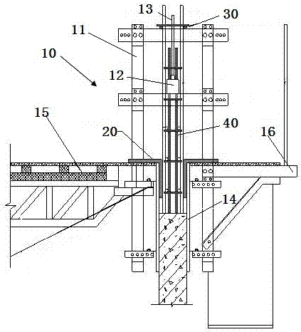
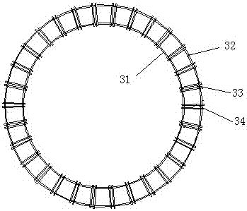
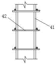
[0035] Such as Figure 1-4As shown, the structural schematic diagram of each device used in the dynamic control method for steel bar installation quality for silo slipform construction in the preferred embodiment of the present invention, in the silo slipform construction method of the present invention, L-shaped round steel 20 is used to control For the thickness of the concrete cover, the "circular grid" vertical steel bar locator 30 is used to control the radial and circumferential horizontal...


PUM


Abstract

The invention discloses a rebar mounting quality dynamic control method used for silo slip-form construction. The method includes the following steps: setting up a slip-form system; fixing L-shaped round steel; determining a vertical rebar positioner, and fixing the same on a lifting frame in the shape of a Chinese character 'Kai' meaning opening; making a horizontal rebar positioner, and pre-burying the horizontal rebar positioner in concrete of the wall of a silo; enabling the L-shaped round steel and the vertical rebar positioner to synchronously slide upwards along with the slip-form system; connecting the horizontal rebar positioner insufficient in length; binding an intersection of a vertical rebar and a horizontal rebar stably by using tie wires. Specially-made rebar positioners including an L-shaped rebar protecting layer position, the annular-network type vertical rebar positioner and the crawling-ladder type horizontal rebar positioner are adopted, so that the mounting and positioning problem of the wall of the silo is solved; compared with conventional processes of using concrete cushion blocks to guarantee thickness of a rebar concrete protecting layer and using a manual binding mode to guarantee interval of transverse rebars and vertical rebars, the method has the advantages of accurate rebar positioning, operation simplicity, reliable quality and low cost and has good popularization and application prospect.

Description

technical field [0001] The invention relates to the technical field of building construction, in particular to a dynamic control method for steel bar installation quality used in silo sliding form construction. Background technique [0002] In the construction field, the slipform construction technology is a special construction technology widely used in the construction of towering cast-in-place concrete structures. Compared with conventional construction methods, this construction technology has the advantages of high degree of mechanization, fast construction speed, less site occupation, strong structural integrity, good seismic performance, safe operation, significant environmental and economic comprehensive benefits, and can save formwork. And the materials needed to build the scaffolding, the formwork can be easily disassembled and assembled flexibly, and can be reused. [0003] Usually, the method of installation of reinforcement works in silo slipform construction i...

Claims


Application Information

Patent Timeline
Patent Type & Authority Patents(China)
IPC IPC(8): E04G11/22E04C5/16
Inventor 李慧莹赵自亮梁智欣
Owner GUANGZHOU HENGSHENG CONSTR ENG
Why Eureka
Try Eureka