A hydraulic shock absorber

A technology of hydraulic shock absorber and gland, applied in the field of hydraulic shock absorber, can solve the problems of troublesome assembly, complex structure, leakage, etc., and achieve the effects of saving man-hours, reducing labor intensity and reducing rework rate

Active Publication Date: 2017-05-10
ZHUZHOU CSR TIMES ELECTRIC CO LTD
View PDF1 Cites 0 Cited by
  • Summary
  • Abstract
  • Description
  • Claims
  • Application Information

AI Technical Summary

Problems solved by technology

The shock absorber is a single-circulation structure of oil. There is an oil hole on the piston. A one-way valve plate is provided between the end face of the piston and the end face of the piston rod. When the piston rod is stretched and compressed, the oil must flow through the guide and then be The metal oil guide pipe guides the flow to the damping valve placed on the base, which can also be adjusted externally, but this structure is destined to only realize the symmetrical characteristics of the tension and compression damping forces, and the tension and compression damping forces cannot be adjusted externally separately, so when external adjustment is required Asymmetrical damping characteristics and tensile and compressive damping forces will be limited when they need to be adjusted separately. In addition, the structure is more complicated. One end of the metal oil guide tube is connected to the guide and the other end is connected to the base. The joints at both ends are sealed with O-rings. When assembling It is more troublesome, when the high-pressure oil discharged from the cylinder flows through the connection at both ends of the metal oil guide pipe, it is easy to cause leakage

Method used


Image

  • A hydraulic shock absorber
  • A hydraulic shock absorber
  • A hydraulic shock absorber

Examples


Embodiment Construction

[0031] The present invention will be further described in detail below in conjunction with the drawings and specific embodiments of the specification.

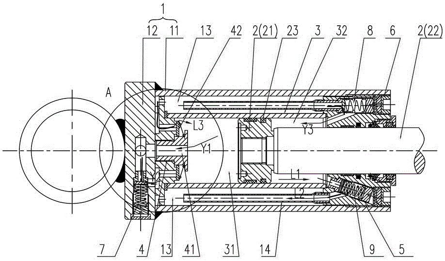
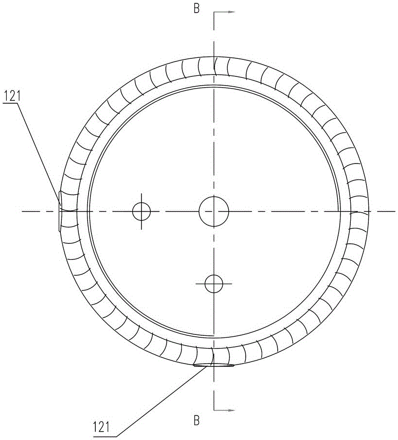
[0032] Figure 1 to Figure 7 An embodiment of the oil pressure damper of the present invention is shown. The oil pressure damper includes an oil storage cylinder 1, a piston assembly 2, a working oil cylinder 3, a bottom valve assembly 4, a guide assembly 5 and a gland 6, and The cylinder 1 includes an outer cylinder 11 and a base 12 fixed to the front end of the outer cylinder 11. The working cylinder 3 is located in the outer cylinder 11 and forms an oil storage chamber 13 between the outer cylinder 11 and the bottom valve assembly The cover 4 is arranged at the front end of the working oil cylinder 3 and abuts against the base 12. The guide assembly 5 is arranged at the rear end of the working oil cylinder 3, the gland 6 is arranged at the rear end of the cylinder body 11, and the piston assembly 2 includes The piston 21 and ...


PUM


Abstract

The invention discloses an oil damper. The oil damper comprises an oil storage cylinder, a piston assembly, a work oil cylinder, a bottom valve assembly, a guide assembly and a gland. The oil storage cylinder comprises an outer cylinder body barrel and a base. An oil storage cavity is formed between the work oil cylinder and the outer cylinder body barrel. The guide assembly is arranged at the rear end of the work oil cylinder. The end, away from a piston, of a piston rod of the piston assembly penetrates out of the guide assembly and the gland outwards, and the piston divides the work oil cylinder into a first cavity and a second cavity. The base is provided with a compressing damping regulation valve, the inlet of the compressing damping regulation valve is communicated with the first cavity, and the outlet of the compressing damping regulation valve is communicated with the oil storage cavity. The guide assembly is provided with a stretching check valve and a stretching damping regulation valve, the inlet of the stretching check valve is communicated with the oil storage cavity, the outlet of the stretching check valve is communicated with the second cavity, the inlet of the stretching damping regulation valve is communicated with the second cavity, and the outlet of the stretching damping regulation valve is communicated with the oil storage cavity. The bottom valve assembly is provided with a one-way check valve. The oil damper has the advantages that the stretching and compressing damping force can be symmetric or asymmetric, can be independently adjusted and can be externally adjusted.

Description

Technical field [0001] The invention relates to the technical field of vibration reduction of railway locomotives and vehicles, in particular to a hydraulic shock absorber. Background technique [0002] Railway locomotive oil pressure shock absorber is a key component of rail transportation equipment such as EMUs, electric locomotives, diesel locomotives, subway trains, etc. Its function is to reduce the vibration of rolling stock during the driving process, ensure the safety of rolling stock, and improve train comfort degree. [0003] The internal structure of hydraulic shock absorbers is generally divided into one-way oil circulation structure and two-way oil circulation structure. Single-cycle structure shock absorbers have symmetrical tensile and compression damping characteristics, and the symmetry cannot be changed by the damping control valve , The damping control valve of this structure is designed at the assembly of the guide and there is no need to disassemble the intern...

Claims


Application Information

Patent Timeline
Patent Type & Authority Patents(China)
IPC IPC(8): F16F9/516F16F9/19
Inventor 曾松林黎剑锋王凯平陈健方照根熊求颛宋光伟陈永军言珊
Owner ZHUZHOU CSR TIMES ELECTRIC CO LTD
Why Eureka
Try Eureka