Microstrip rectifying antenna

A technology of rectenna and microstrip feeder, which is applied to antennas and electrical components, can solve the problems of low conversion efficiency, high processing cost, and difficulty in integration, and achieve high conversion efficiency, low cost, and easy array formation

Inactive Publication Date: 2016-01-13
UNIV OF ELECTRONICS SCI & TECH OF CHINA
View PDF1 Cites 7 Cited by
  • Summary
  • Abstract
  • Description
  • Claims
  • Application Information

AI Technical Summary

Problems solved by technology

[0005] The purpose of the present invention is to propose a microstrip rectenna to overcome the shortcomings of exi

Method used


Image

  • Microstrip rectifying antenna
  • Microstrip rectifying antenna

Examples


Embodiment Construction

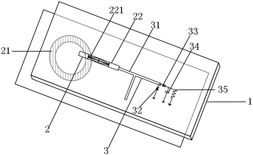
[0017] The present invention will be further described below in conjunction with accompanying drawing and specific embodiment: figure 1 As shown, a microstrip rectenna includes a dielectric substrate 1 , and a receiving antenna 2 and a rectifier circuit 3 printed on both sides of the dielectric substrate 1 . The dielectric substrate 1 is an RF35 dielectric substrate with a thickness of 0.508mm, a dielectric constant of 3.5, a loss tangent of 0.0018, and a copper layer thickness of 0.018mm. The size is 100*50mm; the diameter of the selected metallized through hole is 0.8mm. The receiving antenna 2 includes a ring slot 21 and a microstrip feeder 22 , and the rectifying circuit 3 includes a matching circuit 31 , a first rectifying diode 32 , a second rectifying diode 33 , a bypass capacitor 34 and an output load 35 . The receiving antenna 2 is connected to the input end of the matching circuit 31 through the microstrip feeder 22, and the output end of the matching circuit 31 is c...


PUM


Abstract

The invention discloses a microstrip rectifying antenna. The microstrip rectifying antenna includes a dielectric substrate as well as a receiving antenna and a rectifying circuit printed at two sides of the dielectric substrate; since microstrip lines of a compact microstrip resonant unit are loaded on the receiving antenna so as to perform coupling excitation on an annular groove, harmonic radiation loss of the antenna can be avoided; and the rectifying circuit is of a series-parallel voltage-multiplying circuit structure, so that the rectifying circuit can be small in size and compact in structure and has high conversion efficiency. The microstrip rectifying antenna of the invention can be used for a microwave energy transmission system and a space microwave energy collection system. The microstrip rectifying antenna of the invention can satisfy requirements of systems for plane miniaturization, portability, low cost, easiness in integration and high conversion efficiency.

Description

technical field [0001] The invention belongs to the field of wireless energy transmission, in particular to a microstrip rectifying antenna. Background technique [0002] With the increasing shortage of non-renewable resources such as oil and coal, the development of new energy has attracted more and more attention from the international community. In 1968, Dr. Glaster of the United States first proposed the concept of space solar power generation, and one of the key technologies to realize this concept is energy transmission, namely Microwave energy transmission technology (MicrowavePowerTransmission, MPT). With the development of modern semiconductor technology and integrated electronic technology, MPT technology is gradually applied to low-power electronic devices, such as micro-energy harvesting systems, radio frequency identification systems and biomedical devices. [0003] The rectenna is one of the most critical parts of the MPT technology, and its performance will a...

Claims


Application Information

Patent Timeline
IPC IPC(8): H01Q23/00
Inventor 林先其康湛毓江源聂丽瑛梅鹏陈哲许冬冬黄登祥
Owner UNIV OF ELECTRONICS SCI & TECH OF CHINA
Why Eureka
Try Eureka