Drawer push-in interlocking mechanism

A technology of interlock mechanism and drawer, which is applied in the direction of pull-out switchgear, switchgear, electrical components, etc., and can solve problems such as drawer skew, large transmission ratio, and large tolerance of guide rails.

Active Publication Date: 2016-01-13
ZHEJIANG JINLU ELECTRICAL
View PDF4 Cites 1 Cited by
  • Summary
  • Abstract
  • Description
  • Claims
  • Application Information

AI Technical Summary

Problems solved by technology

However, due to the large tolerance of the guide rails, the drawer has a large plug insertion resistance. When the drawer is connected to the busbar, the drawer will be skewed and mechanically damaged, which will affect the use.
[0005] The Chinese patent application number 201510413991.0 discloses a drawer push interlock mechanism for low-voltage power distribution cabinets, including a first gear, a second gear, shrapnel and a locking mechanism. The first gear meshes with the second gear to form the main components of the push mechanism The components are only driven by two gears, the transmission ratio is large, and the second gear is connected to the bracket transmission, it is easy to cause misalignment of the two gears, and it needs to be recalibrated to correspond to the positional relationship of the three positions; because the two gears mesh with each other, the shaking Turning the first gear drives the rotation of the second gear. Therefore, it is necessary to provide the sum of the rotational torque of the first gear and the second gear to promote the rotation of the two and increase the speed at which the user consumes physical strength; the locking lever in the locking mechanism is initially locked. It will be inserted into the layer partition under the drawer under the action of its own gravity, which will affect the normal push of the drawer

Method used


Image

  • Drawer push-in interlocking mechanism
  • Drawer push-in interlocking mechanism
  • Drawer push-in interlocking mechanism

Examples


Embodiment Construction

[0028] The present invention will be further described with reference to the accompanying drawings and examples.

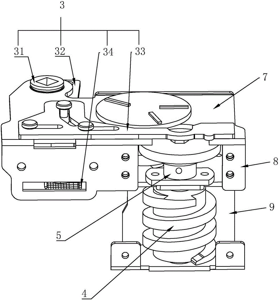
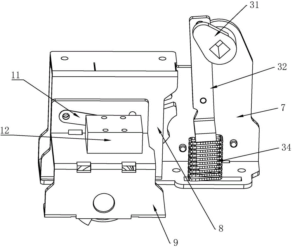
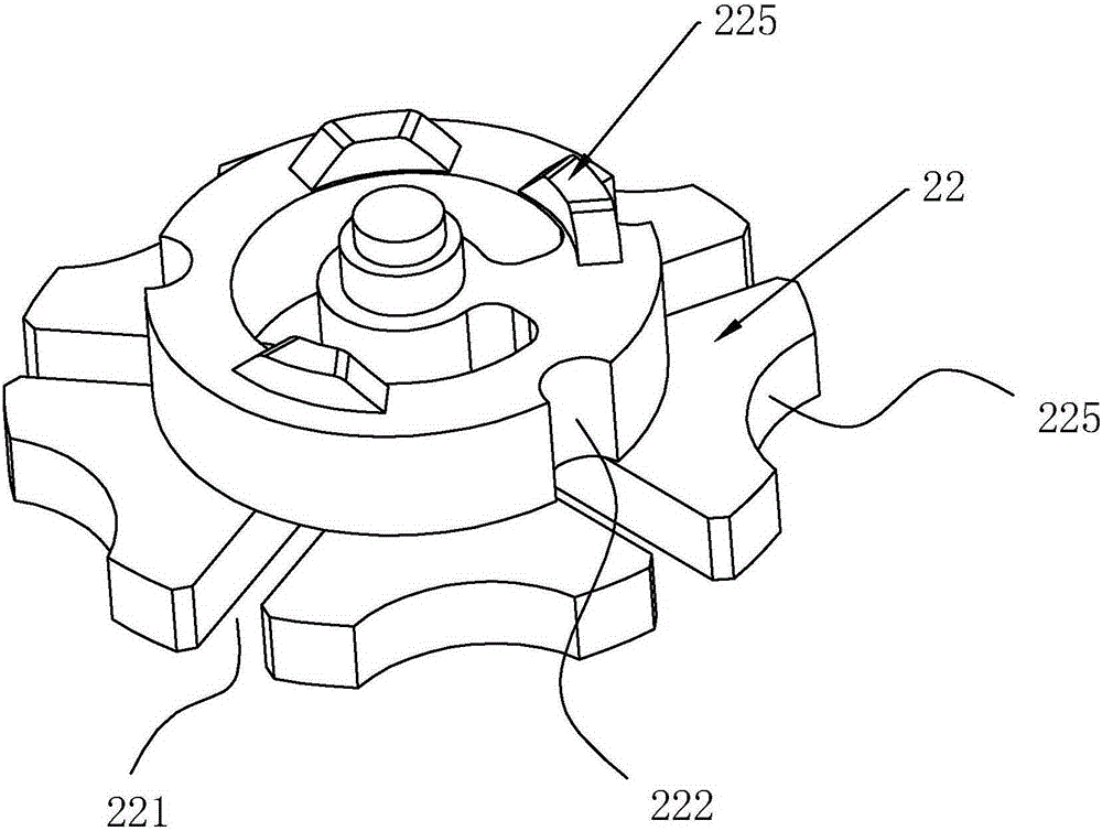
[0029] A drawer push interlocking mechanism, comprising a front bracket 7, a middle bracket 8, a rear bracket 9 and a travel switch 12, a front cavity is formed between the front bracket 7 and the middle bracket 8, and a dial wheel 21, Driven wheel 22, trigger device 1 and the fixed elastic locator 23 for dial wheel 21 are in connection, experiment, separation, on driven wheel 22 (as image 3 ) is composed of a first round table and a second round table with a smaller radius than the first round table. There are five toggle grooves 221 evenly distributed on the first round table. The end face of the dial wheel 21 opposite to the driven wheel 22 is provided with a dial rod 211. The dial rod 211 Place it in the next toggle groove 221 after every rotation, the rear cavity is formed between the middle and rear brackets 9, and a turbine 4 is arranged in the rear cavity...


PUM


Abstract

The present invention discloses a drawer push-in interlocking mechanism. The drawer push-in interlocking mechanism comprises a turbine, a drive unit configured to drive the rotation of the turbine. The drive unit comprises a star wheel, a driven wheel and an elastic locating piece configured to be fixed when the star wheel is in connection, experiment or separation states. The driven wheel is provided with a plurality of driving slots. The end face of the star wheel, with respect to the driven wheel, is provided with a driving lever configured to shift into the driving slots so as to drive the rotation of the driven wheel. According to the invention, the drives of the star wheel and the driven wheel take the place of the gear drive, and the drawer push-in interlocking mechanism has low cost, easy assembling and stable pushing.

Description

technical field [0001] The present invention relates to a low-voltage drawer type switchgear, more specifically, it relates to a drawer push interlocking mechanism. Background technique [0002] Withdrawable low-voltage power distribution cabinet has the advantages of saving space, reliable operation, convenient installation and maintenance, strong breaking capacity, and many outlet circuits, etc. It is widely used in power distribution systems in power plants, substations, factories and mines, and high-rise buildings. middle. The main function of the power distribution cabinet is to convert, distribute and control power for power distribution, motor control and lighting power distribution equipment. [0003] Due to the special working characteristics of the power distribution cabinet, the power distribution industry has strict requirements on the design of the power distribution cabinet. In the withdrawable low-voltage power distribution cabinet, the drawer of each circui...

Claims


Application Information

Patent Timeline
Patent Type & Authority Applications(China)
IPC IPC(8): H02B11/133
CPCH02B11/133
Inventor 施成勇
Owner ZHEJIANG JINLU ELECTRICAL
Why Eureka
Try Eureka