Mutual inductor insulating oil degassing device and degassing method thereof

A degassing device and transformer technology, applied in chemical instruments and methods, liquid degassing, separation methods, etc., can solve the problems of increasing the difficulty of degassing, increasing secondary pollution, lowering the oil level, etc., to prevent secondary contamination, reduced exposure time, elimination of the effect of lower oil levels

Active Publication Date: 2016-01-20
STATE GRID CORP OF CHINA +2
View PDF6 Cites 2 Cited by
  • Summary
  • Abstract
  • Description
  • Claims
  • Application Information

AI Technical Summary

Problems solved by technology

[0003] The traditional transformer degassing method has the following defects and deficiencies: in step 1, since the oil is exposed to air and discharged, it is very likely that gas and moisture will be mixed in the discharge process, which increases the difficulty of degassing; in step 2, the transformer core The submersible has been in direct contact with the air, which increases the possibility of secondary pollution; in step 3, the insulating oil is generally at a high temperature of about 60°C. After cooling and standing still, the oil level may drop or even the oil level gauge will not show. number, negative pressure and other adverse working conditions appear in the transformer; step 4 is mainly to remove the moisture and gas in the core of the transformer, but because the gas has been immersed in the core, the filtering effect may not be ideal, and it needs to be carried out Long vacuum filtration may achieve the expected effect; in step 5, since the whole process of oil injection and hot oil circulation is in a high temperature environment, after standing for cooling, it is very likely that the low oil level and internal Negative pressure and other issues

Method used


Image

  • Mutual inductor insulating oil degassing device and degassing method thereof
  • Mutual inductor insulating oil degassing device and degassing method thereof

Examples


Embodiment Construction

[0027] The present invention will be further described in detail below in conjunction with the accompanying drawings and specific embodiments.

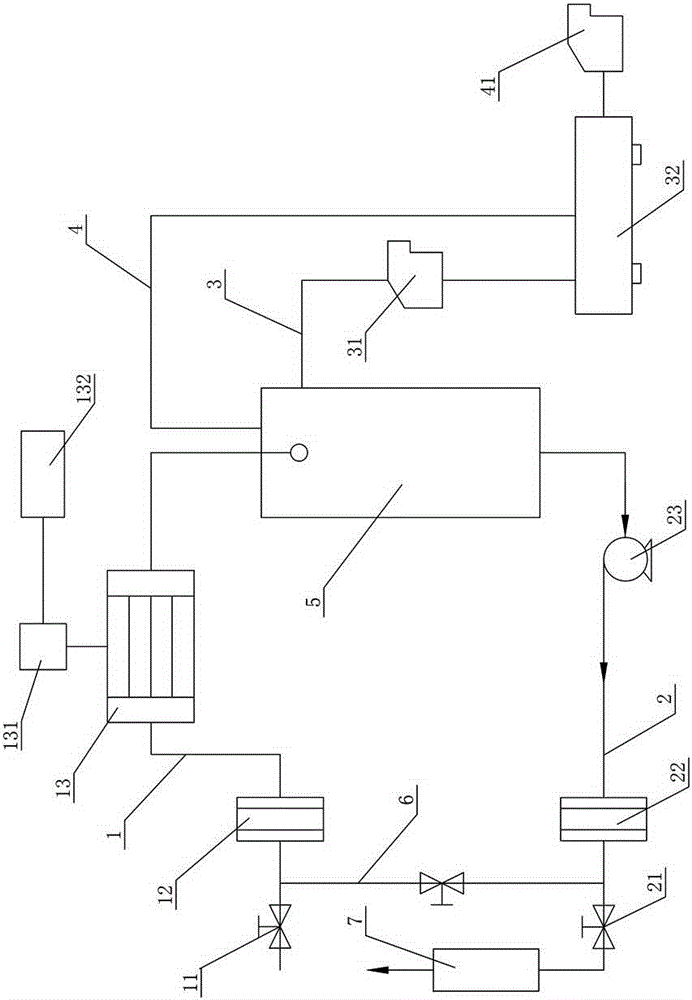
[0028] Such as figure 1 As shown, an embodiment of the transformer insulating oil degassing device of the present invention includes a vacuum flash tower 5 and an oil inlet pipeline 1 connected to the vacuum flash tower 5, an oil outlet pipeline 2, a drain pipeline 3 and an exhaust gas The pipeline 4, the oil inlet pipeline 1 and the oil outlet pipeline 2 are respectively connected with the transformer, the oil inlet pipeline 1 and the oil outlet pipeline 2 are provided with a bypass pipeline 6, and the oil outlet pipeline 2 is provided with a cooler 7. In this structure, before degassing, the oil outlet pipeline 2 can be docked with the vent plug on the upper part of the expander of the transformer, and the bypass pipeline 6 and the oil inlet pipeline 1 can be opened to absorb the insulating oil in the expander to prevent formal dega...


PUM


Abstract

The invention discloses a mutual inductor insulating oil degassing device and a degassing method thereof. The device comprises a vacuum flasher, and an oil inlet pipeline, an oil outlet pipeline, a drainage pipeline and an exhaust pipeline which are connected with the vacuum flasher, wherein the oil inlet pipeline and the oil outlet pipeline are respectively butted with the mutual inductor; a bypass pipeline is arranged between the oil inlet pipeline and the oil outlet pipeline; and a cooler is arranged on the oil outlet pipeline. The method comprises the following steps: S1, absorbing oil of an expander of the mutual inductor; S2, degassing and butting; S3, degassing; S4, cooling; and S5, discharging oil. The device disclosed by the invention has the advantages that the operation is simple, the core of the mutual inductor can be prevented from being polluted, and the filtering and degassing effects are good.

Description

technical field [0001] The invention mainly relates to a power transformer maintenance technology, in particular to a transformer insulating oil degassing device and a degassing method thereof. Background technique [0002] The traditional transformer degassing process is mainly divided into the following steps: 1. First discharge the oil in the transformer to an oil container; 2. Perform hot oil circulation on the insulating oil for a sufficient time; 3. Dispose of the qualified insulating oil Inject into the transformer to the appropriate oil level; 4. Continue to carry out hot oil circulation on the oil in the transformer for a sufficient time; 5. Shut down, stand still and test. [0003] The traditional transformer degassing method has the following defects and deficiencies: in step 1, since the oil is exposed to air and discharged, it is very likely that gas and moisture will be mixed in the discharge process, which increases the difficulty of degassing; in step 2, the ...

Claims


Application Information

Patent Timeline
Patent Type & Authority Applications(China)
IPC IPC(8): B01D19/00
Inventor 董卓程青山
Owner STATE GRID CORP OF CHINA
Why Eureka
Try Eureka