Waste gas dedusting device and method for tunnel kiln

A technology of a dust removal device and a tunnel kiln, which is applied in the chemical industry, can solve the problems of poor dust removal and filtering effect, poor particle removal ability, and difficulty in cleaning, etc., and achieves the effect of reducing water loss, simple installation and good dust removal rate.

Active Publication Date: 2016-01-20
盐城易动科技服务有限公司
View PDF4 Cites 6 Cited by
  • Summary
  • Abstract
  • Description
  • Claims
  • Application Information

AI Technical Summary

Problems solved by technology

[0003] In industrial production, dust removal devices used to treat industrial waste gas emissions can be mainly divided into dry dust removal devices and wet dust removal devices. Dry dust removal devices include gravity settling chambers, cyclone dust collectors, multi-tube cyclone dust collectors, and filter bag dust collectors. , high-voltage electrostatic precipitators, self-shielding dust collectors, etc., wet dust collectors such as impact water bath dust collectors, water film dust collectors and various spray structures. Especially the ability to remove particles is poor; the widely used dust collector in the existing cement industry production is the impact-spray combined dust collector, but its equipment is relatively complicated and it is not easy to clean, and the dust collector can only remove finer particles. dust

Method used


Image

  • Waste gas dedusting device and method for tunnel kiln
  • Waste gas dedusting device and method for tunnel kiln

Examples


Embodiment 1

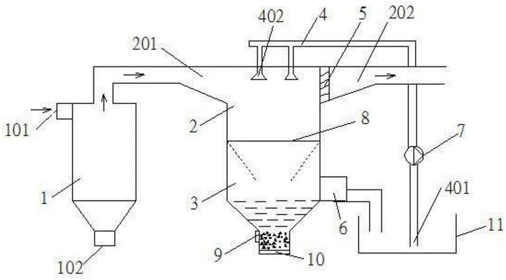
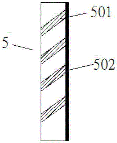
[0032] Open the atomizing shower 4, the switchable partition 8 at the entrance of the dust collection chamber 3 and the switch at the outlet of the purifier 6. The dust concentration passed into the exhaust gas inlet 101 of the cyclone separator 1 is 2483 mg / m 3 The simulated tunnel kiln exhaust gas, the average particle size of the dust in the exhaust gas is 0.8um, the exhaust gas enters the entrance channel 201 of the spray chamber 2 after the first-stage dust removal of the cyclone separator 1; the first-stage dust removal exhaust gas fills the spray chamber 2, and is atomized The sprinkler 4 performs secondary dust removal, the spray water pressure is 140kPa, and the waste gas from the secondary dust removal flows to the outlet channel 202 through the ventilation baffle 5 . The measured dust concentration at the outlet is 317mg / m 3 . The dust removal rate is 87.2%.

[0033] Most of the water produced by atomization spraying flows into the dust collection chamber 3 throu...

Embodiment 2

[0036] Open the atomizing shower 4, the switchable partition 8 at the entrance of the dust collection chamber 3 and the switch at the outlet of the purifier 6. The dust concentration of the cyclone separator 1 inlet 101 is 3822mg / m 3 The simulated tunnel kiln exhaust gas, the average particle size of the dust in the exhaust gas is 18.0um, the exhaust gas enters the entrance channel 201 of the spray chamber 2 after passing through the cyclone separator 1 first-stage dust removal; the first-stage dust removal exhaust gas fills the spray chamber 2, and is atomized The sprinkler 4 performs secondary dust removal, the spray water pressure is 160kPa, and the waste gas from the secondary dust removal flows to the outlet channel 202 through the ventilation baffle 5 . The measured dust concentration at the outlet is 563mg / m 3 . The dust removal rate is 85.2%.

[0037] Most of the water produced by the atomization spray flows into the dust collection chamber 3 through the switchable ...


PUM

PropertyMeasurementUnit
dust removal efficiencyaaaaaaaaaa

Abstract

The invention relates to a waste gas dedusting device and method for a tunnel kiln. The dedusting device comprises a cyclone separator for performing primary dedusting on waste gas, a spraying chamber and a dust collection chamber, wherein the spraying chamber is connected with the cyclone separator and used for performing secondary dedusting on the waste gas; the dust collection chamber is arranged at the lower end of the spraying chamber, communicated with the spraying chamber and used for concentrated treatment of secondary dedusting dust; a waste gas inlet, a primary dedusting dust discharge port and a primary dedusting waste gas outlet are formed in the cyclone separator; an atomization sprayer for performing spraying dedusting on primary waste gas, a primary dedusting waste gas inlet and a secondary dedusting waste gas outlet are formed in the spraying chamber; an inlet channel and an outlet channel which extend obliquely towards the dust collection chamber are formed in the primary dedusting waste gas inlet and the secondary dedusting waste gas outlet of the spraying chamber respectively. The dedusting method comprises primary dedusting by the cyclone separator and secondary dedusting by the atomization sprayer. The cyclone separator and the atomization sprayer are combined for use, dust falling is specifically performed on dust in the waste gas, and the dedusting effect is excellent.

Description

technical field [0001] The invention relates to a dust removal device and a dust removal method, in particular to a tunnel kiln waste gas dust removal device and a dust removal method, belonging to the technical field of chemical industry. Background technique [0002] To control the air pollution of coal-fired tunnel kilns, we should mainly start from two aspects: one is to improve the combustion method and technology, so that all the combustible substances in the fuel can be burned and released inside the kiln as much as possible to avoid the formation of carbon black and residual carbon; It is to carry out smoke and dust control, that is, to use various dust collectors to separate and recycle the smoke and dust in the exhaust gas; in addition to effectively reducing environmental pollution and increasing environmental benefits, the above method can also save resources and reduce burning energy consumption; and then The recovered dust can be used as raw materials in produc...

Claims


Application Information

Patent Timeline
Patent Type & Authority Applications(China)
IPC IPC(8): B01D50/00
Inventor 姜瑞雨朱涛许宁侯贵华黄建军
Owner 盐城易动科技服务有限公司
Why Eureka
Try Eureka