Servo control based multilayer flame laminating mechanism

A technology of flame compounding and servo control, which is applied in the direction of controlling lamination, lamination, lamination device, etc., can solve the problems of different shrinkage, material wrinkling, and no major improvement in the production compounding process, so as to achieve overall quality improvement , surface smoothness, and the effect of avoiding changes in the amount of retraction

Active Publication Date: 2016-01-20
YANCHENG XUHUA MACHINERY
View PDF6 Cites 3 Cited by
  • Summary
  • Abstract
  • Description
  • Claims
  • Application Information

AI Technical Summary

Problems solved by technology

In the clothing, furniture and other industries, two-layer materials were used to be composited, but now the amount of three-layer composite materials with sponge in the middle is increasing, but the production composite process has not been greatly improved. At present, the two-layer flame with a single burner structure is still used. Composite machines are mainly used, and the composite needs to be completed in two times. However, the control deviation of the material tension and the amount of flame injection in the two composite processes is relatively large, resulting in different shrinkage after the two flame composites, which makes the material wrinkle. This not only The production efficiency is low, and the composite quality cannot be guaranteed
In order to solve the above problems, the scientific and technical personnel of the scientific research institutes have continuously researched and explored, and developed a three-layer flame laminating machine with double burners. Although certain progress has been made in technology, there are still technical problems that have not yet been overcome in practical application.

Method used


Image

  • Servo control based multilayer flame laminating mechanism
  • Servo control based multilayer flame laminating mechanism
  • Servo control based multilayer flame laminating mechanism

Examples


Embodiment 1

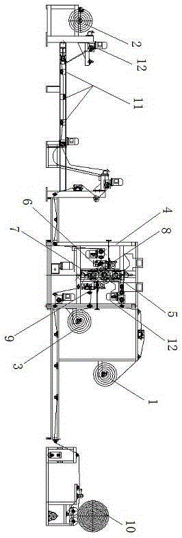
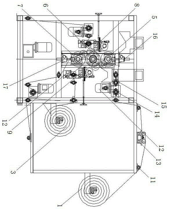
[0030] like figure 1 and figure 2 A servo-controlled multi-layer flame composite mechanism is shown, which includes a discharge mechanism, a flame composite mechanism and a material receiving mechanism; a grass-roots spreader 1 for placing grass-roots raw materials is arranged in the discharge mechanism, The first fabric expander 2 for placing the first fabric fibers and the second fabric expander 3 for placing the second fabric fibers, the base layer expander 1, the first fabric expander 2 and the second fabric expander The cloth devices 3 all use three-roller cloth expanders, the base material is sponge, and the first fabric fibers and the second fabric fibers can be any textiles.

[0031] The flame recombination mechanism includes a main frame 4, and the first water-cooled roll 5, the second water-cooled roll 6 and the third water-cooled roll 7 are arranged in the main frame 4 in order in the vertical direction, wherein the first water-cooled roll 5 is in contact with th...

Embodiment 2

[0041] As an improvement of the present invention, such as figure 1 and figure 2As shown, in the discharging mechanism, the servo traction devices corresponding to the grass-roots cloth expander 1 and the first fabric expander 2 and the second fabric expander 3 respectively include a pneumatic deviation correction device 13 and an opening and closing device. The width device, the opening device includes a rubber rough surface roller 14 and a metal opening roller 15; the pneumatic correction device 13, the rubber rough surface roller 14 and the metal opening roller 15 are set up in sequence along the direction of the raw material. With the above-mentioned design, it can keep the base material / fabric fiber above the set transmission direction in real time during the transmission process through the setting of the pneumatic deviation correction device, so as to avoid its deviation during the transmission process, thus causing the base material and fabric fiber The fabric fibers...

Embodiment 3

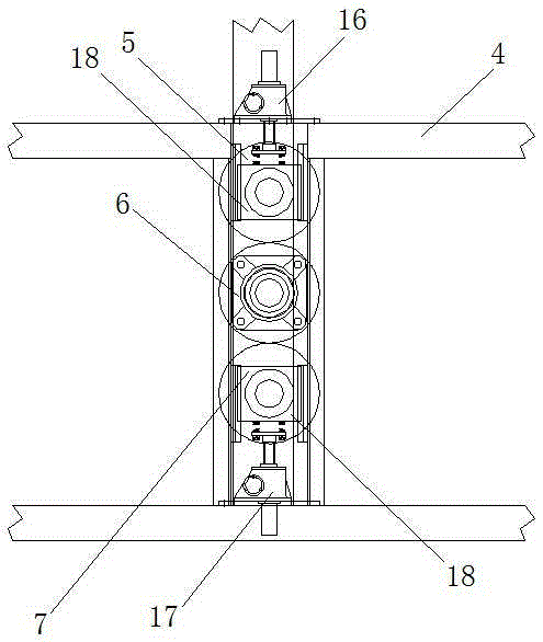
[0044] As an improvement of the present invention, such as image 3 and Figure 4 As shown, the first water-cooled roll 5, the second water-cooled roll 6 and the third water-cooled roll 7 are connected to each other; the main frame 4 is provided with a step-up and lowering device, which includes the first water-cooled roll 5 The upper hydraulic cylinder 16 above, and the lower hydraulic cylinder 17 arranged below the third water-cooled roller 7, the push rods of the upper hydraulic cylinder 16 and the lower hydraulic cylinder 17 all extend vertically, and they are respectively connected to the first water-cooled roller 5 And the third water-cooled rollers 7 are connected to each other. With the above-mentioned design, it can make the first water-cooled roller, the second water-cooled roller and the third water-cooled roller The position in the vertical direction can be adjusted. Since the tension generated by multiple water-cooled rollers on the base material / fabric fibers ...


PUM


Abstract

The invention discloses a servo control based multilayer flame laminating mechanism. The servo control based multilayer flame laminating mechanism comprises a discharging mechanism, a flame laminating mechanism body and a receiving mechanism. A base-layer cloth pay-off device and multiple fabric pay-off devices are arranged in the discharging mechanism. The flame laminating mechanism body comprises a main machine frame, wherein multiple pairs of water cooling rollers are arranged in the main machine frame, and one flame jet device is arranged between any one pair of water cooling rollers and the corresponding fabric pay-off devices respectively. The fabric pay-off devices and the base-layer cloth pay-off device are respectively and correspondingly provided with a servo traction device, the water cooling rollers are controlled through a servo motor, and the servo motor is mutually and electrically connected with a traction servo motor in a servo traction system. The servo control based multilayer flame laminating mechanism adopting the technical scheme can achieve synchronous processing of multilayer composite materials through the structural layout of all mechanisms and accordingly can be applicable to efficient production of complicated composite materials.

Description

technical field [0001] The invention relates to a textile processing device, in particular to a multilayer flame composite mechanism based on servo control. Background technique [0002] The flame laminating machine is a processing equipment that has emerged with the deep processing of textiles in recent years. It is suitable for laminating sponges with other textiles, non-woven products, plush, chicken skin and other materials; the flame laminating machine uses The sponge body is used as an adhesive material, and its surface is melted at high temperature by flame spraying, and then compounded with other materials. Composite materials have the advantages of high speed and integrity, good hand feeling, resistance to dry cleaning and water washing, etc. In the clothing, furniture and other industries, two-layer materials were used to be composited, but now the amount of three-layer composite materials with sponge in the middle is increasing, but the production composite proce...

Claims


Application Information

Patent Timeline
Patent Type & Authority Applications(China)
IPC IPC(8): B32B37/04B32B41/00
CPCB32B37/04B32B41/00
Inventor 卞定华董新民顾卫玲卞丹丹
Owner YANCHENG XUHUA MACHINERY
Why Eureka
Try Eureka