
Water-pressure separation type methane-generating tank

A separate, biogas digester technology, applied in the field of biogas digesters, can solve the problems of difficulty in discharging solids and low utilization rate of raw materials.

Inactive Publication Date: 2016-01-20
CHONGQING BAIJIASI BIOGAS EQUIP
View PDF0 Cites 0 Cited by
  • Summary
  • Abstract
  • Description
  • Claims
  • Application Information

AI Technical Summary

Problems solved by technology

[0006] The purpose of the present invention is to provide a hydraulic separation biogas digester, which adopts the method of separate feeding of solid and liquid to solve the problems of low raw material utilization rate and difficult solid discharge

Method used


Image

  • Water-pressure separation type methane-generating tank

Examples


Embodiment Construction

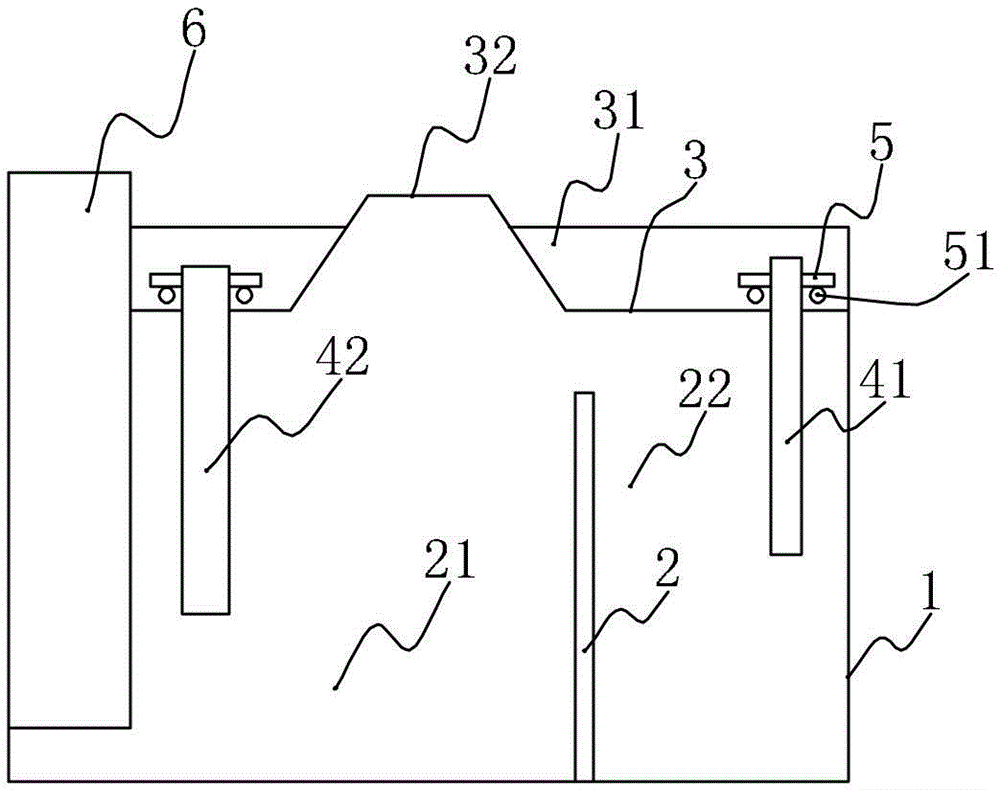
[0015] Such as figure 1 As shown, the hydraulic separation biogas digester of the present invention includes a pond body 1 , and a vertical baffle 2 is arranged at the bottom of the pond body 1 . The baffle 2 divides the bottom area of ​​the cell 1 into two separate parts. Among them, the two independent parts are divided into two areas, one large and one small. The larger area is the solid area 21 and the smaller area is the liquid area 22 . Wherein, a cover plate 3 is provided on the top of the pool body 1, and a hydraulic pool 31 is provided on the cover plate 3, and a biogas port 32 is provided in the middle of the cover plate 3. In addition, a liquid inlet pipe 41 is inserted in the liquid area 22 , and the upper end of the liquid inlet pipe 41 is located in the water pressure pool 31 . A slag feeding pipe 42 is inserted in the solid area 21 , and the upper end of the slag feeding pipe 42 is also located in the hydraulic pool 31 . Moreover, the diameter of the slag fe...


PUM


Abstract

The invention relates to a water-pressure separation type methane-generating tank. The water-pressure separation type methane-generating tank is characterized in that a tank body is provided with a cover plate; the cover plate is provided with a water-pressure tank and a methane opening higher than the water-pressure tank; a baffle plate is arranged at the bottom part of the tank body and separates the tank body into a solid area and a liquid area with non-communicated bottom parts; a slag feeding pipe and a slag discharging pipe are inserted into the solid area; a liquid feeding pipe is inserted into the liquid area; the lower end part of the liquid feeding pipe is lower than the top part of the baffle plate; the upper end part of the slag discharging pipe is higher than the top part of the water-pressure tank; floating devices are arranged on the slag feeding pipe and the liquid feeding pipe and are positioned in the water-pressure tank. The water-pressure separation type methane-generating tank has the advantages that solid slag is introduced into the solid area by the slag feeding pipe, liquid materials are introduced into the liquid area by the liquid feeding pipe, and the solid slag in the solid area is positioned at the bottom part and can not enter the liquid area; after fermentation, since the solid slag is not completely utilized, the liquid materials are pumped out by the liquid feeding pipe, the solid slag is remained, and new liquid materials are introduced for repeated fermentation, so that the utilization rate of the solid slag can be increased, solid and liquid can be effectively separated and pumped, and the utilization rate can be increased.

Description

technical field [0001] The invention relates to a biogas digester, in particular to a water pressure separation type biogas digester. Background technique [0002] Biogas is a combustible gas produced by microbial fermentation of organic matter in an anaerobic environment under certain conditions of temperature, humidity, and pH. Because this gas was first found in swamps, lakes, and ponds, people called it biogas. [0003] Biogas contains a variety of gas components, the main component is methane. The process in which biogas bacteria decompose organic matter and produce biogas is called biogas fermentation. According to the role of various bacteria in the biogas fermentation process, biogas bacteria can be divided into two categories. The first type of bacteria is called decomposing bacteria, and its function is to decompose complex organic matter into simple organic matter and carbon dioxide. Among them, there are bacteria that specialize in decomposing cellulose, call...

Claims


Application Information

Patent Timeline
IPC IPC(8): C12M1/107C12M1/00
CPCC12M21/04C12M23/34C12M29/00Y02E50/30
Inventor 廖佳袁
Owner CHONGQING BAIJIASI BIOGAS EQUIP
Learn More