Novel rare-earth electrolytic bath

An electrolytic cell and rare earth technology, applied in the electrolytic process, electrolytic components, electrodes, etc., can solve problems such as inability to adjust, constant change of pole distance, heat loss in open electrolytic cells, etc., to achieve automatic feeding control and lower cell voltage , to solve the effect of heat loss

Active Publication Date: 2016-01-20
CENT SOUTH UNIV
View PDF5 Cites 17 Cited by
  • Summary
  • Abstract
  • Description
  • Claims
  • Application Information

AI Technical Summary

Problems solved by technology

The invention also realizes a closed structure, which effectively solves the problems of tail gas collection and heat loss of open electrolytic cells
The electrolytic cell with this structure overcomes the problems of the traditional rare earth electrolytic cell that the pole distance changes continuously and cannot be adjusted during the electrolysis process. It is very convenient to adjust the pole distance th

Method used


Image

  • Novel rare-earth electrolytic bath
  • Novel rare-earth electrolytic bath
  • Novel rare-earth electrolytic bath

Examples


Embodiment 1

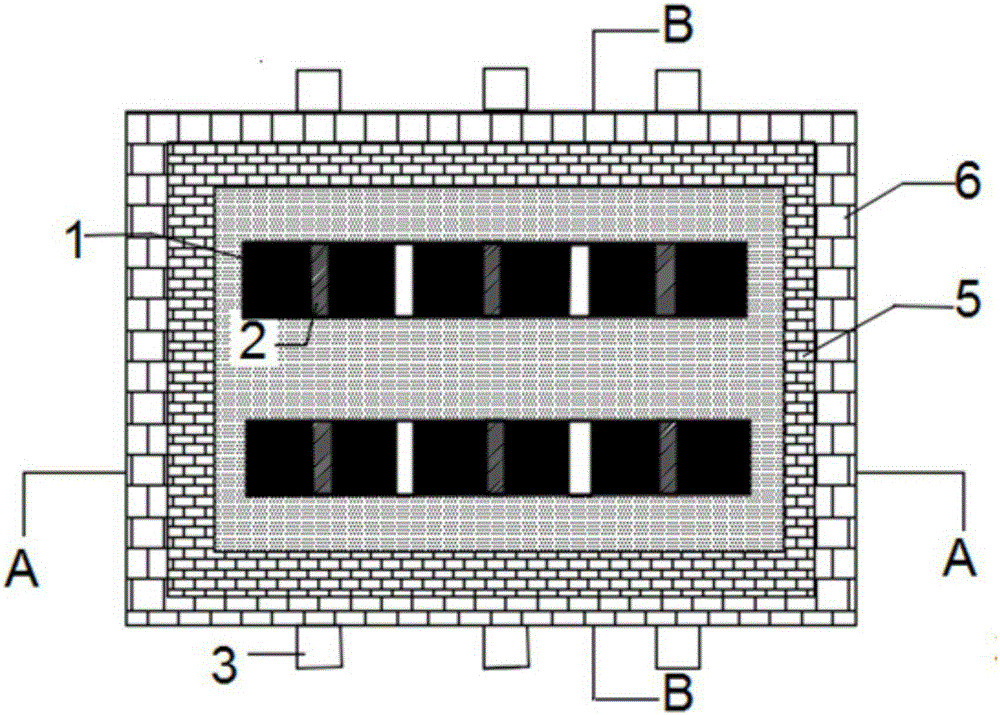
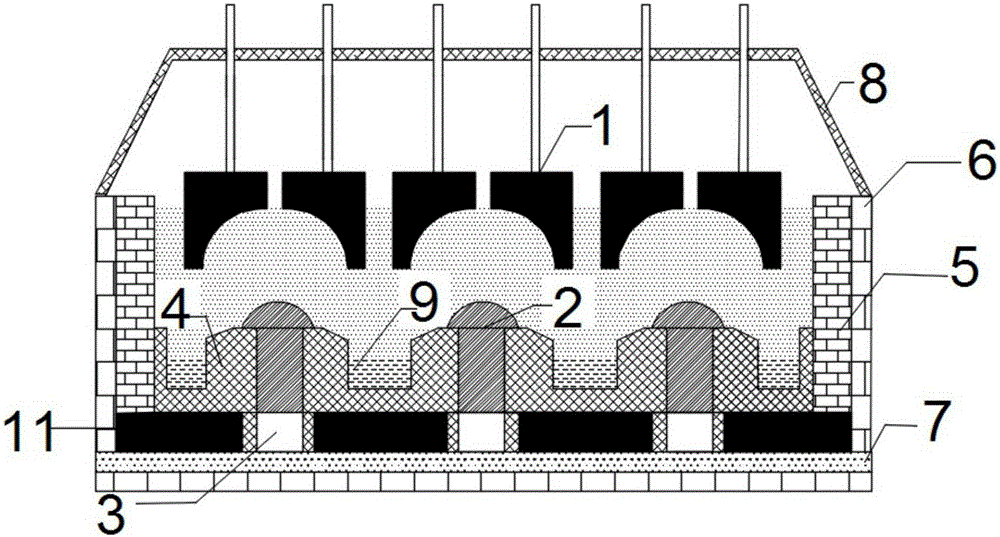
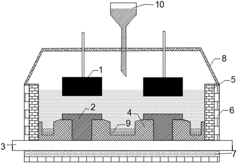
[0027] see figure 1 , figure 2 , image 3 In this embodiment, the cathode is placed under the anode, the bottom of the anode is an arc-shaped concave surface, and the top of the cathode is an arc-shaped convex surface. An anode in this embodiment is composed of two anode blocks, and a gap is left between the two anode blocks , Through the combination of the concave surface and the gap, the air bubbles can be discharged more quickly without staying at the bottom of the anode. In this embodiment, 6 anodes and corresponding 6 cathodes are arranged in the electrolytic cell. The anode is graphite and the cathode is tungsten. The cathode is buried in the raised high-temperature insulating material, and criss-cross metal grooves made of high-temperature insulating material are formed between the cathodes to collect liquid metal. The bottom of the cathode is connected with the cathode steel rod. Each cathode steel rod in this embodiment The rod connects the two cathodes of the sa...

Embodiment 2

[0029] see Figure 4 In this embodiment, the cathode is placed under the anode, the bottom of the anode is an arc-shaped concave surface, and the top of the cathode is an arc-shaped convex surface. In this embodiment, 6 anodes and 6 cathodes are arranged on the upper part of the electrolytic cell, which are divided into two rows. Each row has corresponding 3 anodes and 3 cathodes. In this embodiment, the 3 anodes in a row are composed of 4 anode blocks. The two anode blocks in the middle are T-shaped, and the two anode blocks on both sides are inverted L-shaped. , The assembled anode leaves a gap above the cathode, through the combination of the concave surface and the gap, the air bubbles are discharged more quickly without staying at the bottom of the anode. The anode is graphite and the cathode is molybdenum. The cathode is embedded in the protruding metal material, criss-cross metal grooves made of metal material are formed between the cathodes to collect liquid metal, an...

Embodiment 3

[0031] In this embodiment, the cathode is placed under the anode, the bottom of the anode is an arc-shaped concave surface, and the top of the cathode is an arc-shaped convex surface. An anode in this embodiment is composed of two anode blocks, and a gap is left between the two anode blocks. Through the combination of the concave surface and the slit, the air bubbles can be discharged more quickly without staying at the bottom of the anode. In this embodiment, 6 anodes and corresponding 6 cathodes are arranged in the electrolytic cell. The anode is graphite and the cathode is carbon. The cathode is buried in the raised high-temperature insulating material, and criss-cross metal grooves made of high-temperature insulating material are formed between the cathodes to collect liquid metal. The bottom of the cathode is connected with the cathode steel rod. Each cathode steel rod in this embodiment The rod connects the two cathodes of the same column. Graphite blocks are filled be...


PUM


Abstract

The invention relates to a novel rare-earth electrolytic bath. A gap is reserved in the center of each anode, and the bottom surface of each anode is a concave surface being concave from the periphery towards the center. A cathode is correspondingly arranged below each anode. The cathodes are buried in a protruding high-temperature-resisting material. The top of each cathode is an arc convex surface and protrudes out of the high-temperature insulating material. An electrical insulating layer is arranged between the high-temperature-resisting material and each cathode. A metal groove is formed between every two cathodes, and the high-temperature-resisting material is concave downwards to form the metal grooves. A cathode steel bar is located at the bottom of each cathode and connected with the cathode. The space between every two adjacent cathode steel bars is filled with a graphite block. An electrical insulating layer is arranged between each graphite block and the corresponding cathode steel bar. A feeder is arranged on the top of a bath body. According to the novel rare-earth electrolytic bath, the convex surfaces of the cathodes are higher than the high-temperature insulating layers, so that a high-temperature zone of the electrolytic bath is moved upwards. Through the metal grooves designed for the electrolytic bath, the contact area of metal and an electrolyte is reduced, re-dissolution of the metal is restrained, and the current efficiency is improved. The shapes of the anodes of the electrolytic bath are beneficial for discharging of anode bubbles.

Description

technical field [0001] The invention belongs to the field of rare earth molten salt electrolysis, and in particular relates to a novel rare earth electrolytic cell. Background technique [0002] At present, the upper opening of the electrolytic cell for industrial production of rare earth metals is open, and the cathode and anode are arranged parallel and vertically on the cylindrical surface. This structure leads to low production efficiency of rare earth metal electrolysis, serious environmental pollution, large fluctuations in process parameters, and difficulty in realizing large-scale and automation, which seriously hinders the further development of rare earth electrolysis technology. Studies have shown that: the open radiation heat dissipation of the rare earth electrolyzer with the current structure accounts for 44.5% of the total heat expenditure, which leads to the electrolyzer having to maintain the heat balance of the electrolyzer through high voltage. When the v...

Claims


Application Information

Patent Timeline
IPC IPC(8): C25C3/34C25C7/00C25C7/02
Inventor 吕晓军双亚静许真铭
Owner CENT SOUTH UNIV
Why Eureka
Try Eureka