
Multi-girder section steel-doublelayer concrete bridge deck composite beam implementing technology

A double-layer concrete and bridge deck technology, which is applied in bridges, bridge parts, bridge construction, etc., can solve the problems of multiple processes, long cycle time, and high noise, and achieve the effects of broad application prospects, light weight, and fast speed

Inactive Publication Date: 2016-01-20
CHINA MAJOR BRIDGE ENERGINEERING
View PDF6 Cites 14 Cited by
  • Summary
  • Abstract
  • Description
  • Claims
  • Application Information

AI Technical Summary

Problems solved by technology

[0004] (1) The construction of the full house support method occupies the road area of ​​the existing line, which is likely to cause traffic interruption on the existing road or the reduction of the road width, the traffic capacity is reduced, and it is easy to cause traffic congestion, and there are many construction procedures on site, the noise is large, the construction speed is slow, and the cycle is long , have a great impact on the work and life of the surrounding residents;
[0005] (2) The prefabricated small box girder is erected by the bridge erecting machine method, which can only be advanced hole by hole in one direction, the construction progress is slow, and the transition cost is high. The bridge erection bridge needs to be disassembled and reassembled. The weight of the box girder often reaches 70-150t. The transportation of the box girder is subject to many factors, which may easily cause traffic congestion and may cause damage to existing roads and bridges;
[0006] (3) To install steel box girders in blocks and sections by car cranes or crawler cranes, it is also necessary to set up temporary supports for the welding connection of steel girders. A large number of on-site welding is not conducive to ensuring the quality of steel girders, and a large number of welding sparks will cause passing vehicles and pedestrians Caused a great safety hazard, and poor structural economy

Method used


Image

  • Multi-girder section steel-doublelayer concrete bridge deck composite beam implementing technology
  • Multi-girder section steel-doublelayer concrete bridge deck composite beam implementing technology
  • Multi-girder section steel-doublelayer concrete bridge deck composite beam implementing technology

Examples


Embodiment Construction

[0024] The present invention will be described in detail below in conjunction with the accompanying drawings.

[0025] The concrete steps that the present invention implements are as follows:

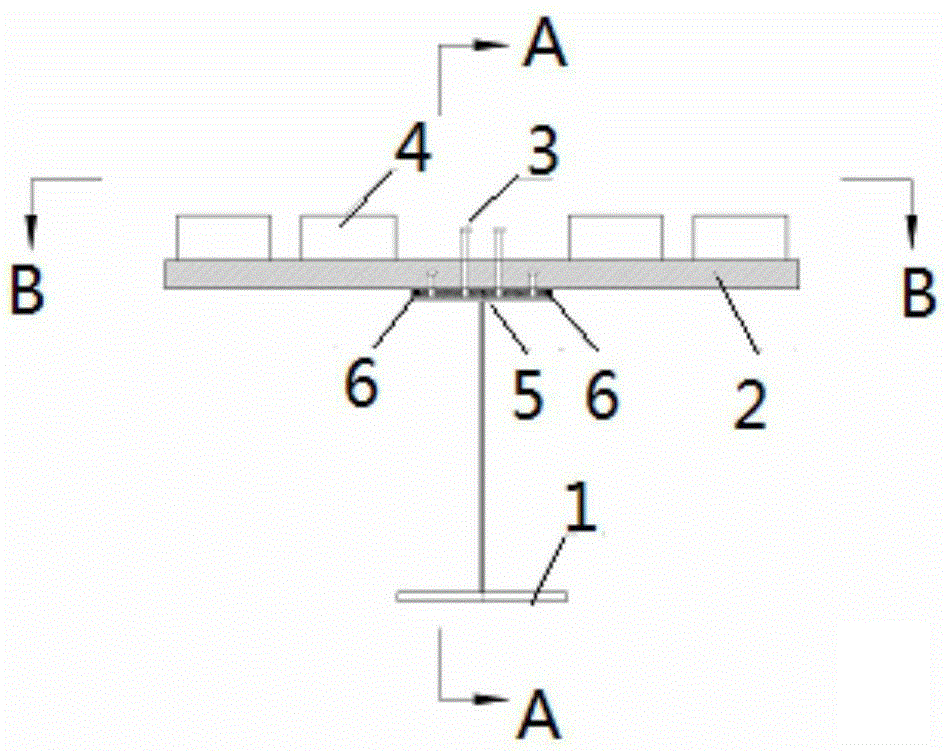
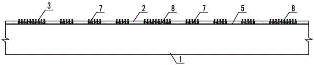
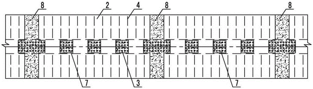
[0026] 1) Weld shear studs 3 on the top of the upper flange plate of "I" shaped steel 1 to form a shear stud group (see figure 1 ); In the factory modular production base plate reinforcement mesh 9 (see Figure 4 ), utilizing the bottom reinforcement mesh 9 to prefabricate the bottom prefabricated concrete bridge deck 2 in the factory, wherein the anchorage reinforcement 4 is exposed;

[0027] 2) Paste elastic rubber strips 6 on the edge of the upper flange plate of the "I" shaped steel, and pour epoxy mortar leveling layer 5 between the elastic rubber strips (see figure 1 );

[0028] 3) Lift and install the bottom prefabricated concrete bridge deck 2, pour micro-expansion concrete 7 and longitudinal wet joint concrete 8 in the shear nail grooves between the bottom concrete bridge de...


PUM


Abstract

The invention relates to a multi-girder section steel-doublelayer concrete bridge deck composite beam implementing technology; the technology comprises the following steps: firstly welding shearing force nails on top edge of each H-shape section steel; combining with a bottom concrete bridge deck, and reserving anchor bars on the bottom concrete bridge deck; using a truck crane to transversely mount composite beams formed by the H-shape section steels and bottom concrete bridge decks one by one hole-to-hole, using elastic rubber strips to seal slab joints between the composite beams, using the bottom concrete bridge deck as a template, binding a top deck steel network with the anchor bars, and finally casting-in-situ an upper concrete slab on the bottom concrete bridge deck; the upper concrete slab and the bottom concrete bridge deck are connected through the anchor bars and the shearing force nails, thus forming the multi-girder section steel-doublelayer concrete bridge deck composite beam; the technology considers design, making, construction, and economic factors, is light in weight, fast in speed, short in period, less in land occupation, low in noises, so city original transport cannot be affected, thus providing wide prospect in the municipal bridge application.

Description

technical field [0001] The invention relates to a rapid implementation technology of a municipal bridge, in particular to an implementation technology of a multi-girder type steel-double-layer concrete bridge deck composite girder. Background technique [0002] With the rapid development of my country's economy in recent years, the number of cars has increased exponentially year by year, the traffic volume of urban roads has increased sharply, and the contradiction between supply and demand between vehicles and roads has become more and more acute. To solve the increasingly prominent problem of urban traffic congestion, it is often Measures such as expanding the original road or transforming the original road are adopted, and road reconstruction often adopts the combination of new viaducts and ground roads. [0003] At present, the main girder forms used in municipal viaducts mainly include: integrally cast-in-place large box girder, prefabricated small box girder or T-beam, ...

Claims


Application Information

Patent Timeline
Patent Type & Authority Applications(China)
IPC IPC(8): E01D21/00E01D19/12
Inventor 张强高宗余罗扣肖海珠王东晖王为玉别业山颜兆福郑清刚李少骏欧阳涛蔡敦松
Owner CHINA MAJOR BRIDGE ENERGINEERING
Features
  • Generate Ideas
  • Intellectual Property
  • Life Sciences
  • Materials
  • Tech Scout
  • Unparalleled Data Quality
  • Higher Quality Content
  • 60% Fewer Hallucinations
Learn More