
Method for measuring working fluid level of rod-pumped well

A technology for pumping wells and measurement methods, applied in construction and other directions, can solve the problems of large test error, complicated and cumbersome acquisition of upper and lower static loads, etc.

Inactive Publication Date: 2016-01-20
PETROCHINA CO LTD
View PDF3 Cites 15 Cited by
  • Summary
  • Abstract
  • Description
  • Claims
  • Application Information

AI Technical Summary

Problems solved by technology

At present, the main method of testing the dynamic liquid level of oil wells is the acoustic reflection method. The main problems of this method are: ⑴ manual operation by workers; ⑵ there are certain unsafe factors in the wellhead sounding device; (4) For oil wells with a dynamic liquid surface depth greater than 1000 meters, it is easily affected by some other working conditions, and the test error is relatively large
[0003] In recent years, due to the development of dynamometer test methods, the technology of calculating the dynamic liquid level based on the dynamometer chart has leaped from theory to application, and the trend tracking technology of dynamic liquid level has been gradually established and continuously improved. When calculating the dynamic liquid level of the oil well with the dynamometer diagram, the influence of inertial load, vibration load, friction load and other factors can be effectively eliminated, and the accuracy of the calculation result is relatively high, but at the same time, the acquisition of the upper and lower static loads is more Difficult, once the working condition of the oil well changes, the static load indicator diagram needs to be corrected, and the timeliness is poor. Moreover, when using this method to calculate the dynamic liquid level of the oil well, the influence of casing pressure is not considered, which is very important for the control of casing pressure production. For oil wells, the calculated dynamic liquid level will have a problem of high error

Method used


Image

  • Method for measuring working fluid level of rod-pumped well
  • Method for measuring working fluid level of rod-pumped well
  • Method for measuring working fluid level of rod-pumped well

Examples


Embodiment Construction

[0039] The invention provides a method for measuring the fluid level of pumping wells, which can effectively improve its timeliness under the condition of ensuring the calculation accuracy, and can also be applied to oil wells that control casing pressure production, so that the calculated fluid level is The error is reduced.

[0040] In order to better understand the above technical solutions, the above technical solutions will be described in detail below in conjunction with the accompanying drawings of the specification and specific implementations.

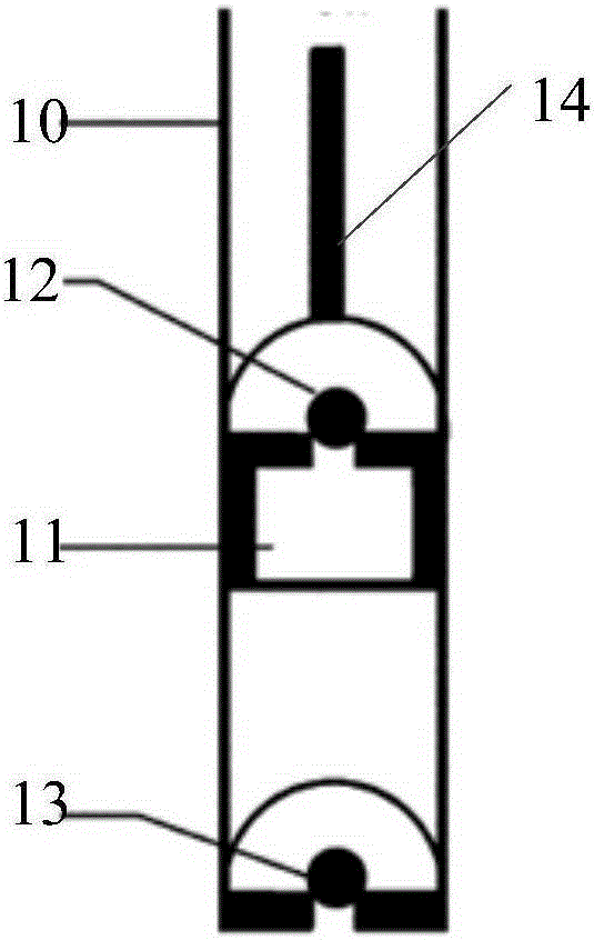
[0041] Before describing the method for measuring the fluid level of a pumping unit well of the present invention, it is first necessary to understand the working principle of the pump. The following is a specific example of a rod pump. For details, see figure 1 , The pump includes a pump cartridge 10, a plunger 11, a traveling valve 12, a fixed valve 13, and a sucker rod 14. During the working process of the pump, the pressure P(t)...


PUM


Abstract

The invention discloses a method for measuring the working fluid level of a rod-pumped well. The method comprises the following steps: according to a drag coefficient calculation model, obtaining a drag coefficient; according to the drag coefficient, a sucker-rod string displacement motion model and a sucker-rod string load calculation model, obtaining displacement parameters at different depths and load parameters of a sucker-rod string, and then obtaining displacement parameters and load parameters of a pump; according to the displacement parameters and the load parameters of the pump, obtaining a pump diagram of the pump; according to the pump diagram and a submergence pressure calculation model as well as a fluid property calculation model, obtaining working fluid level parameters of the rod-pumped well. Through adoption of the method, the measurement timeliness can be effectively improved under the circumstance that the calculation precision is ensured; besides, the method is further applicable to an oil well where casing pressure needs to be controlled for production, so that an error in calculation of the working fluid level can be reduced.

Description

Technical field [0001] The invention relates to the field of petroleum technology, in particular to a method for measuring the fluid level of a pumping unit well. Background technique [0002] The fluid level of the pumping well is an important parameter for understanding the fluid supply of the oil well, diagnosing the fault of the oil well, and evaluating and optimizing the suitability of the oil production process. At present, the main testing method for the fluid level of oil wells is the acoustic reflection method. The main problems of this method are: ⑴ rely on manual operation by workers; ⑵There are certain unsafe factors in the wellhead sound device; ⑶Test once a month and cannot track the fluid online. Changes in the surface; ⑷For oil wells with a working liquid surface depth greater than 1000 meters, they are easily affected by some other working conditions, and the test error is relatively large. [0003] In recent years, due to the development of indicator diagram test...

Claims


Application Information

Patent Timeline
IPC IPC(8): E21B47/047
Inventor 李少甫唐庆韩岐清冯国强马晓雁金满库卢晨
Owner PETROCHINA CO LTD
Learn More