Bevel gear combination bearing for speed reducer

A combined bearing and helical gear technology, applied in the field of bearings, can solve the problems of unstable operation, low bearing capacity, large reducer model, etc., and achieve the effect of compact structure, high bearing capacity and stable operation.

Active Publication Date: 2016-01-20
CSC BEARING
View PDF7 Cites 0 Cited by
  • Summary
  • Abstract
  • Description
  • Claims
  • Application Information

AI Technical Summary

Problems solved by technology

[0003] Affected by the high difficulty of processing the supporting bearings, the existing reducer models are large, bulky, and have complex internal structures, and the bearings have low load-carrying capacity, are easy to wear, have low service life, and are not stable enough during operation

Method used


Image

  • Bevel gear combination bearing for speed reducer

Examples


Embodiment Construction

[0016] The preferred embodiments of the present invention will be described in detail below in conjunction with the accompanying drawings, so that the advantages and features of the present invention can be more easily understood by those skilled in the art, so as to define the protection scope of the present invention more clearly.

[0017] see figure 1 , the embodiment of the present invention includes:

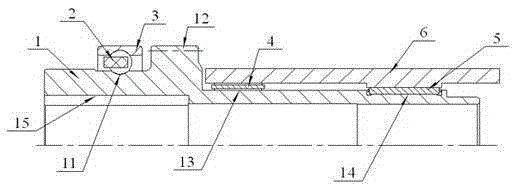
[0018] A helical gear combined bearing for a reducer, comprising: a helical gear main shaft 1, a steel ball and cage assembly 2, an outer ring 3, a first needle roller and cage assembly 4, a second needle roller and cage assembly 5 and a sleeve Barrel 6.

[0019] Wherein, the helical gear main shaft 1 includes a first raceway 11 , a helical gear 12 , a second raceway 13 and a third raceway 14 from front to back.

[0020] The first raceway 11 is a spherical raceway, the steel ball and cage assembly 2 is installed in the first raceway 11, and the outer ring 3 is installed i...


PUM


Abstract

The invention discloses a bevel gear combination bearing for a speed reducer. The bevel gear combination bearing comprises a bevel gear main shaft, a steel ball and cage component, an outer ring, a first rolling needle and cage component, a second rolling needle and cage component, and a sleeve, wherein the bevel gear main shaft comprises a first rolling way, a bevel gear, a second rolling way and a third rolling way from front to back in sequence; the steel ball and cage component is mounted in the first rolling way; the outer ring is mounted on the bevel gear main shaft through the steel ball and cage component; the first rolling needle and cage component is mounted in the second rolling way; the second rolling needle and cage component is mounted in the third rolling way; and the sleeve is mounted on the bevel gear main shaft through the first rolling needle and cage component and the second rolling needle and cage component. Through the mode, the bevel gear combination bearing for the speed reducer is compact in structure, can reduce the type and the weight of the matched speed reducer, improves the bearing capacity of the combination bearing, and can bear a greater torque.

Description

technical field [0001] The invention relates to the technical field of bearings, in particular to a helical gear combined bearing for a speed reducer. Background technique [0002] The reducer is a relatively precise machine, the purpose of using it is to reduce the speed and increase the torque. The reducer is an independent component consisting of gear transmission, worm transmission, and gear-worm transmission enclosed in a rigid shell. It is often used as a reduction transmission device between the original moving part and the working machine. It plays the role of matching speed and transmitting torque between prime mover and working machine or actuator. [0003] Affected by the high difficulty of processing the supporting bearings, the existing reducer models are large, bulky, and have complex internal structures, and the bearings have low load-carrying capacity, are easy to wear, have a low service life, and are not stable enough during operation. Contents of the in...

Claims


Application Information

Patent Timeline
Patent Type & Authority Applications(China)
IPC IPC(8): F16H57/021F16C19/54
CPCF16C19/54F16H57/021
Inventor 王志良沈忠明王中原毛仲武陈志刚杨益农
Owner CSC BEARING
Why Eureka
Try Eureka