
Ultra-narrowband low-noise optoelectronic oscillator

A photoelectric oscillator, low-noise technology, applied in the direction of phonon exciter, circuit, electrical components, etc., can solve the problems that restrict the performance of the phase noise of the oscillator, and achieve the effect of improving the phase noise

Inactive Publication Date: 2016-01-20
CHINA ELECTRONIC TECH GRP CORP NO 38 RES INST
View PDF8 Cites 4 Cited by
  • Summary
  • Abstract
  • Description
  • Claims
  • Application Information

AI Technical Summary

Problems solved by technology

In other words, the limitation of the existing optoelectronic oscillator loop bandwidth on the loop delay length restricts the phase noise performance of the oscillator

Method used

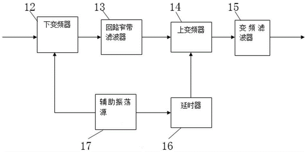

Image

  • Ultra-narrowband low-noise optoelectronic oscillator
  • Ultra-narrowband low-noise optoelectronic oscillator
  • Ultra-narrowband low-noise optoelectronic oscillator

Examples


Embodiment Construction

[0021] The structural features of the present invention will now be described in detail in conjunction with the accompanying drawings.

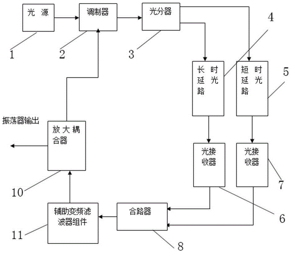
[0022] see figure 2 , an ultra-narrow-band low-noise photoelectric oscillator, including a light source 1, a modulator 2, an optical splitter 3, a long-delay optical path 4, a short-delay optical path 5, a first optical receiver 6, a second optical receiver 7, Electrical combiner 8, amplifying coupler 10, auxiliary conversion filter assembly 11. in,

[0023] The output end of the light source 1 is connected to the input end of the optical splitter 3 via the modulator 2 . The optical splitter 3 divides the received optical signal into two paths, one optical signal is transmitted to the first optical receiver 6 through the long-delay optical path 4 , and the other optical signal is transmitted to the second optical receiver 7 through the short-delay optical path 5 . The output end of the first optical receiver 6 and the output end of the se...


PUM


Abstract

To solve the technical problem that the relative bandwidth of a conventional optoelectronic oscillator is generally not less than one thousandth as the working frequency of the microwave optoelectronic oscillator is high and the relative bandwidth is limited by engineering implementation, the invention provides an ultra-narrowband low-noise optoelectronic oscillator comprising a light source, a modulator, a light splitter, a long-delay light path, a short-delay light path, a first light receiver, a second light receiver, a power combiner, an amplifying coupler, and an auxiliary variable-frequency filter assembly. The beneficial effect is that the situation in which the phase noise performance of the conventional optoelectronic oscillator is constrained by the limitation on the length of loop delay due to wide loop bandwidth is overcome, and a novel method is provided for improving the phase noise of the optoelectronic oscillator.

Description

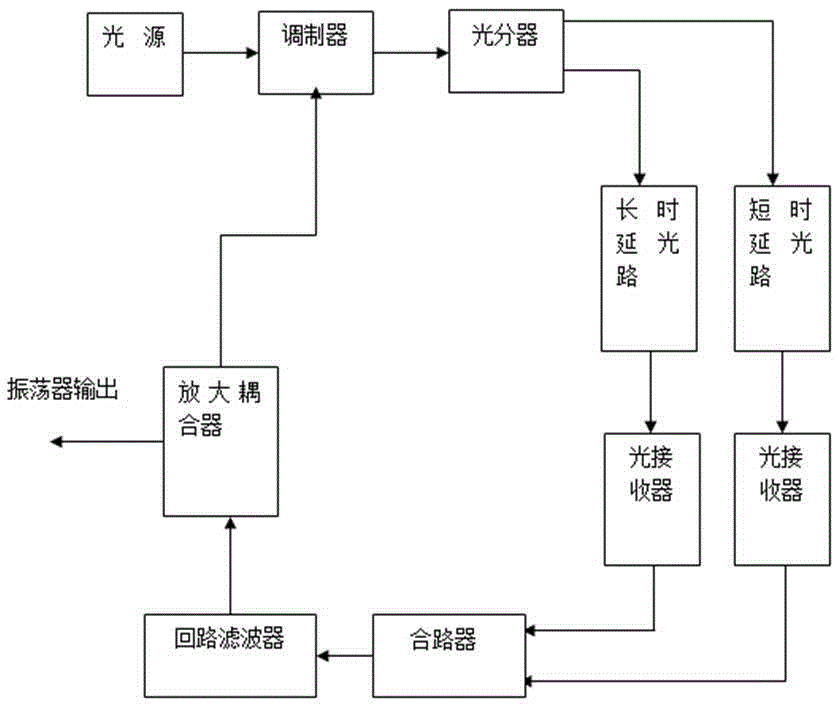
technical field [0001] The invention relates to a photoelectric oscillator technology, in particular to an ultra-narrow-band low-noise photoelectric oscillator. Background technique [0002] The optoelectronic oscillator is a different type of traditional oscillator (such as figure 1 Shown) the invented oscillator, some scholars call it "ultimate oscillator", high frequency, low phase noise characteristics have great technical advantages High (frequency range can cover 1GHz-100GHz); wide tuning range, fast speed, low vibration sensitivity (10 -12 / g). Microwave optoelectronic oscillators may be an important technological revolution in the field of frequency sources, and will provide a new technical path for future high-performance radar and electronic warfare systems. [0003] The phase noise of the optoelectronic oscillator is approximately inversely proportional to the square of the fiber delay, so increasing the delay time of the oscillation loop is an effective means ...

Claims


Application Information

Patent Timeline
Patent Type & Authority Applications(China)
IPC IPC(8): H01S1/00
Inventor 柳勇方立军马骏张焱吉宗海
Owner CHINA ELECTRONIC TECH GRP CORP NO 38 RES INST
Learn More