Brushless DC motor with asymmetric winding

A DC motor, asymmetric technology, applied in the shape/style/structure of the winding conductor, etc., can solve the problems of low motor speed adjustment accuracy, low current density, and motor output power limitation.

Active Publication Date: 2016-01-20
沈阳兴华航空电器有限责任公司
View PDF6 Cites 0 Cited by
  • Summary
  • Abstract
  • Description
  • Claims
  • Application Information

AI Technical Summary

Problems solved by technology

[0002] The existing brushless DC motors work for a long time, and their current density is low. The stator winding is generally wound with a single enameled wire (44), a

Method used


Image

  • Brushless DC motor with asymmetric winding
  • Brushless DC motor with asymmetric winding
  • Brushless DC motor with asymmetric winding

Examples


Embodiment 1

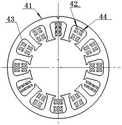
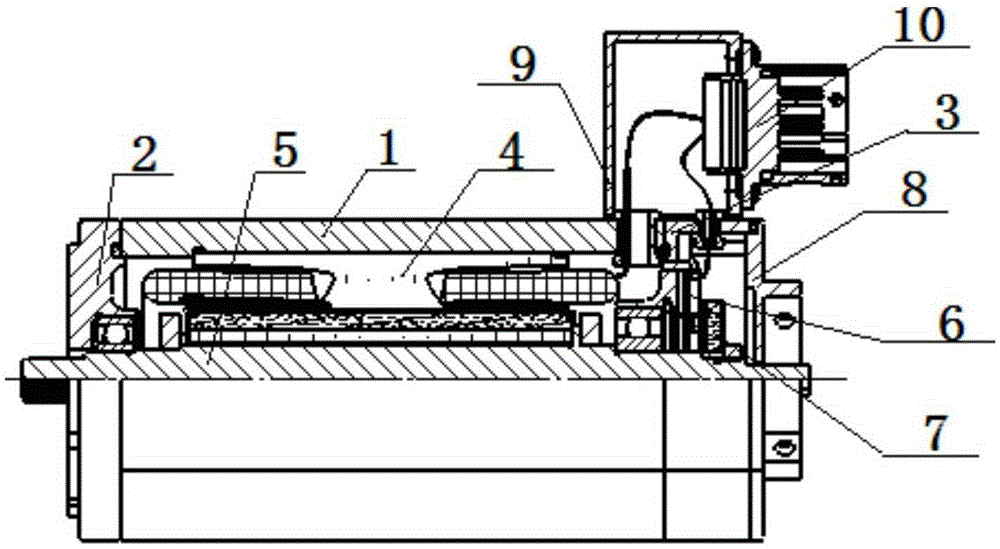
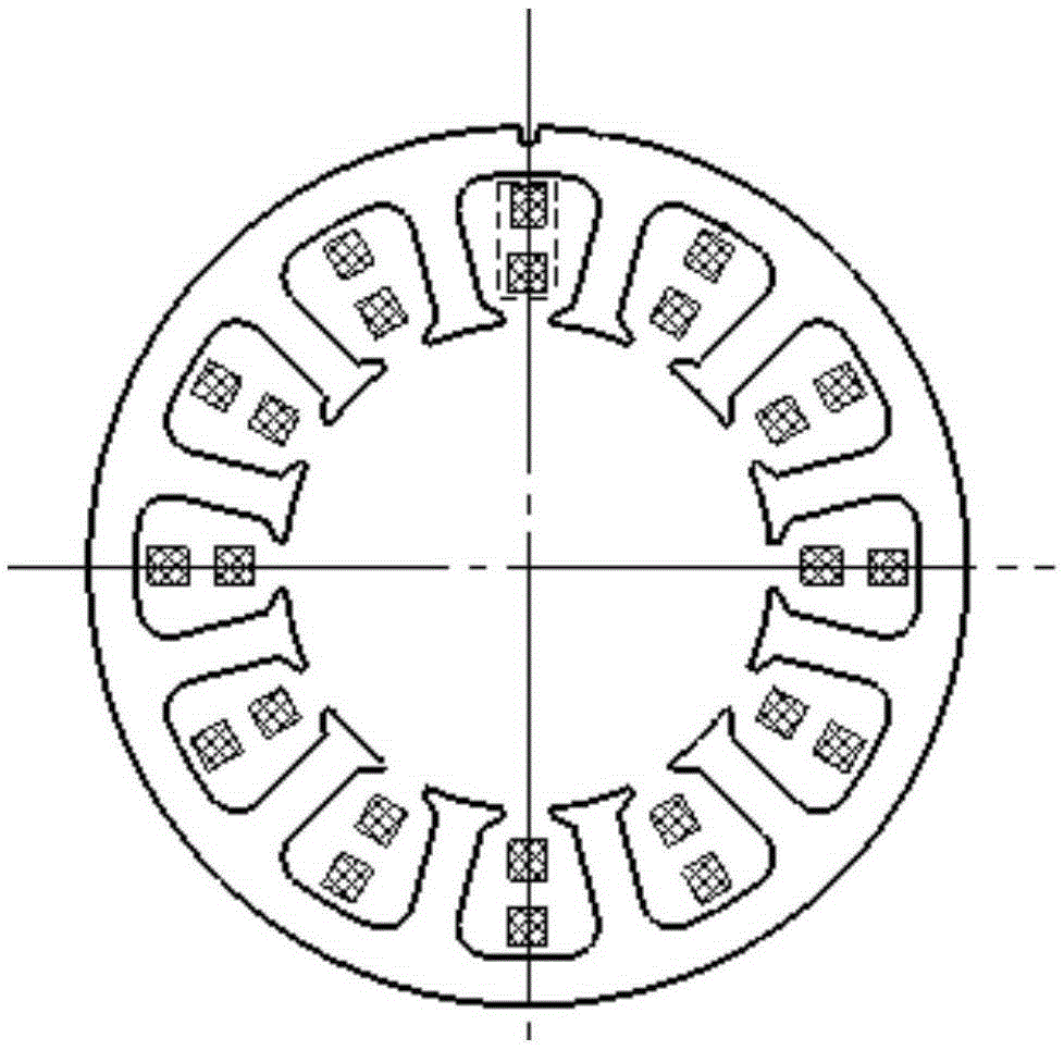
[0016] The brushless DC motor with asymmetric winding is composed as follows: housing 1, front end cover 2, rear end cover 3, stator 4, rotor 5, circuit board assembly 6, sensor rotor 7, sensor rear cover 8, connector base 9 and electrical connector 10; the stator 4 is bonded inside the housing 1, and the stator 4 includes a stator core 41 and a winding 42; the stator core 41 is provided with a stator slot structure 43, and the winding 42 is asymmetrically embedded in the stator slot In the structure 43, the winding 42 is wound by enameled wire 44, the front end cover 2 and the rear end cover 3 are respectively fixedly connected to the two ends of the housing 1, the rotor 5 is connected with the front end cover 2 and the rear end cover 3, the rotor assembly Cooperate with the front end cover and the rear end cover through the bearing. The circuit board assembly is fixed on the rear end cover through screws, and the sensor rotor 7 is connected with the rotor 5 through nuts. Th...


PUM


Abstract

The invention discloses a brushless DC motor with an asymmetric winding. The brushless DC motor with the asymmetric winding comprises the components of a housing, a front end cap, a back end cap, a stator, a rotor, a circuit board assembly, a sensor rotor, a sensor back cover, a connector base and an electric connector. The stator is bonded in the housing. The stator comprises a stator core and a winding. The stator core is provided with stator trough structures. The winding is inlayed in the stator trough structures asymmetrically. According to the stator winding of the brushless DC motor with the asymmetric winding, a parallel winding manner of a plurality of enameled wires is adopted, thereby greatly enlarging a motor current. Under a precondition that the motor size is unchanged, motor power is remarkably improved. For realizing small-amplitude adjustment on the working rotating speed of the motor in a certain range, the numbers-of-turns of the winding in the troughs are different from one another. The asymmetric winding is equivalent with a fractional number-of-turns winding, thereby realizing continuous and adjustable rotating speed of the motor, and ensuring a fact that the motor satisfies a technical requirement.

Description


Claims


Application Information

Patent Timeline
IPC IPC(8): H02K3/12H02K3/28
Inventor 乔春雨杨群张彦修
Owner 沈阳兴华航空电器有限责任公司
Why Eureka
Try Eureka