

Cutting mechanism of disc cutter
A cutting mechanism and cutting machine technology, applied in cutting equipment, agricultural machinery and implements, applications, etc., can solve the problems of large change in resistance torque, intensified vibration, and smaller space between moving knives, etc., and achieve small changes in resistance torque and reduced Vibration frequency, the effect of improving stability
Inactive Publication Date: 2016-01-27
XISHUI QUNXING BREEDING FARMERS SPECIALIZED COOP
View PDF6 Cites 0 Cited by
- Summary
- Abstract
- Description
- Claims
- Application Information
AI Technical Summary
Problems solved by technology
When a moving knife with a straight blade performs sliding cutting, as the cutting edge of the blade moves away from the center of rotation (the center of the cutter head), the sliding cutting angle (the distance between the normal line of any point on the cutting edge curve and the direction of the moving speed of this point) Angle) decreases, the resistance torque changes greatly when cutting, the vibration of the cutting machine is aggravated when the cutting machine is working, and the cutting is laborious and the function consumption is high
[0006] When the disc cutter cuts the crop stalks, one moving knife needs to cut the entire end face of the crop stalks. After the first moving knife leaves the straw, it takes a while for the second moving knife to start cutting and cutting. Such cutting The method has the following defects. The motor load is unstable, which leads to uneven cutting force, which makes the disc cutting machine vibrate greatly and has low stability. It is easy to cause the position of other structures of the disc cutting machine to change, thereby affecting the disc cutting machine. The performance of the machine; at the same time, it emits a lot of noise, causing noise pollution to the environment and seriously affecting the health of the staff
[0007] In recent years, researchers have done a lot of research on the cutting mechanism of disc cutting machines: some have increased the number of moving knives on the cutter head to shorten the interval time between cutting work between the moving knives and reduce vibration. However, since all the moving knives are on the same circumference, the space between the moving knives becomes smaller, which will easily cause the cut straw to fall off the cutter head in time, and there will be post-cut straw, which will cause the moving knife Too many cut straws are accumulated between them and blocked, so that the cutting machine cannot work normally, and it needs to be shut down to clean up, which affects the continuous cutting work; some change the structure of the cutter head, and change the flat circular cutter head into a spiral knife. Disk, the stability of the disk cutter is improved, but the processing cost of such cutterhead is too high
Method used
View moreImage
Smart ImageViewing Examples

Examples
Embodiment Construction
[0020] Below in conjunction with accompanying drawing and embodiment the technical solution of the present invention is further described:
Login to View More PUM
| Property | Measurement | Unit |
|---|---|---|
| Wedge angle | aaaaa | aaaaa |
Abstract
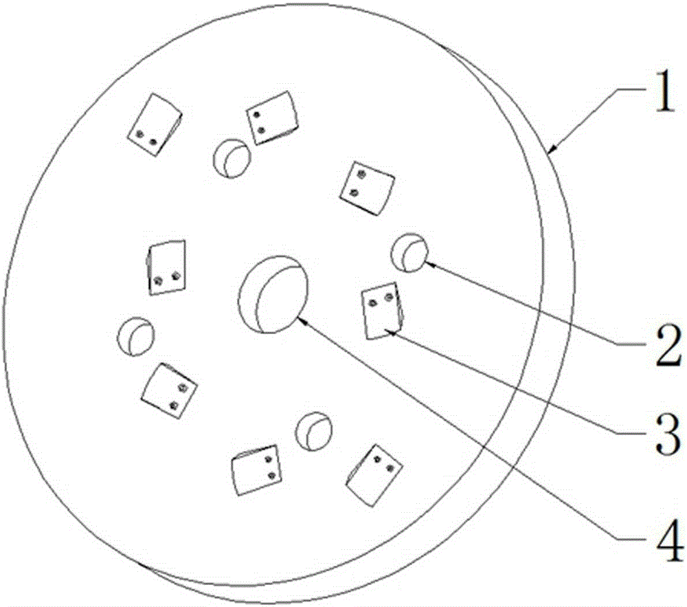
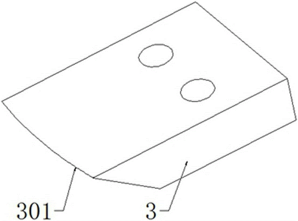
The invention discloses a cutting mechanism of cutting equipment, and specifically relates to a cutting mechanism of a disc cutter. The cutting mechanism comprises a cutter head equipped with moving cutters on the surface, an axis hole in the center of the cutter head, and through holes uniformly distributed on the periphery of the axis hole. The cutter head is equipped with at least two rings of moving cutters with the center of the axis hole as the circular center, at least two moving cutters are arranged on each ring, and the moving cutters on each ring are uniformly distributed on the circumference of the cutter head. The moving cutters on two adjacent rings are not in the same radial direction of the cutter head, and the outer sides of the blades of the moving cutters on the inner ring and the inner sides of the blades of the moving cutters on the outer ring are on the same circumference. The blades of the moving cutters are curve blades with equal sliding-cutting angle. The sliding-cutting angle is 37-45 DEG C. The wedge angle of the moving cutters is 30-40 DEG C. According to the invention, continuous cutting is realized, and the cutting efficiency is improved. The resistance moment borne by the moving cutters during cutting is smooth, the power consumption and vibration are reduced, and the stability is high. The moving cutters are not easily wound with crop straws in the cutting process, the operation quality is improved, and the wear rate of the moving cutters is low.
Description
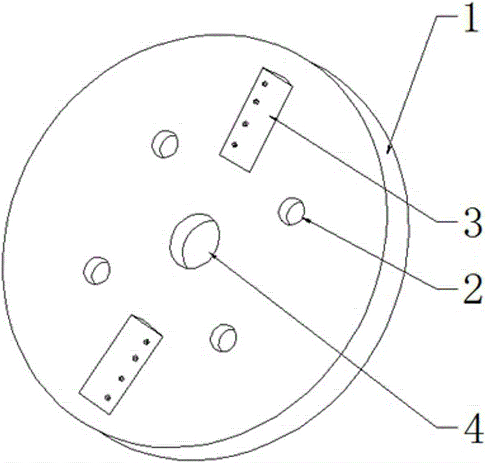
technical field [0001] The invention relates to a cutting mechanism of cutting equipment, in particular to a cutting mechanism of a disc cutter. Background technique [0002] The crop straw cutting machine is a machine used to slice or cut fibrous stalk-like materials such as thatch, corn stalk, sorghum stalk, etc. The main part for cutting is its cutting mechanism, and the structure of the cutting mechanism affects the cutting performance of the cutting machine. [0003] Disc cutting machine is a kind of crop straw cutting machine. The cutting mechanism of the commonly used disc cutting machine is as follows: image 3 As shown, it includes a rotatable cutter head (1), an axis hole (4) for passing through the main shaft on the cutter head (1), and holes for passing through the hammer connecting rod evenly distributed on the outer periphery of the axis hole. The through hole (2) also includes moving knives (3) radially distributed on the surface of the cutter head (1), and th...
Claims
Login to View More Application Information
Patent Timeline
 IPC IPC(8): A01F29/09
Inventor杨德志王明吴大江肖仙佑袁灿陈喆禹仕平
OwnerXISHUI QUNXING BREEDING FARMERS SPECIALIZED COOP