Self-rotation-free traction type stepless speed changer

A continuously variable transmission, traction type technology, applied in the direction of vehicle gearbox, friction transmission device, transmission element, etc., can solve the problems of troublesome speed control, difficult manufacturing, wear of belt and pulley, etc. The effect of convenient speed control and high transmission efficiency

Active Publication Date: 2016-01-27
SICHUAN UNIV
View PDF7 Cites 6 Cited by
  • Summary
  • Abstract
  • Description
  • Claims
  • Application Information

AI Technical Summary

Problems solved by technology

The metal belt type continuously variable transmission has achieved good results in the application of automobiles, but it has three shortcomings: first, the cost of the transmission is relatively high, the metal belt is made of multiple steel sheets, and the number of parts is large. , Assembly and material requirements are very high, resulting in higher cost of the transmission; second, the transmitted torque is small, the metal belt continuously variable transmission transmits power through the friction torque between the pulley and the metal block, and the transmission torque is bound to be affected by the metal belt. The pressure between the belt and the working surface of the pulley and the restriction of the surface friction coefficient make it difficult to achieve high torque output; the third is that wear is likely to occur between the belt and the pulley, which affects the service life of the transmission
Although this traction type continuously variable transmission eliminates the spin, there are two difficulties: one is the complex logarithmic curve of the busbar of the driving cone and the driven cone, which is difficult to manufacture; the other is that the speed control is more troublesome , when the speed is adjusted, the power roller both rotates and moves, and the driving cone and the driven cone will also move along their axes, making it difficult to control the speed

Method used


Image

  • Self-rotation-free traction type stepless speed changer
  • Self-rotation-free traction type stepless speed changer
  • Self-rotation-free traction type stepless speed changer

Examples


Embodiment Construction

[0014] Combine now figure 1 , to describe in detail the specific embodiments of the present invention.

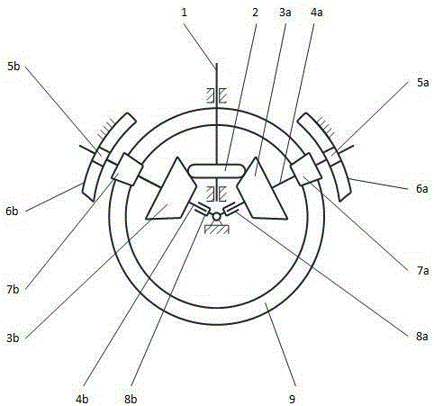
[0015] The non-spin traction continuously variable transmission mainly consists of an input shaft (1), a driving roller (2), a first driven cone (3a), a second driven cone (3b), and a first intermediate shaft (4a) , the second intermediate shaft (4b), the first slider (5a), the second slider (5b), the first guide rail (6a), the second guide rail (6b), the first bevel pinion (7a), the second Small bevel gear (7b), the first swing support (8a), the second swing support (8b) and large bevel gear (9).

[0016] The driving roller (2) is installed on the input shaft (1), and it can move along the axis of the input shaft (1), but cannot rotate relative to the input shaft (1). The driving roller (2) is in the shape of a disk, and its generatrix is ​​in the shape of an arc, and has a simple structure and is easy to manufacture.

[0017] The first driven cone (3a) and the first sm...


PUM


Abstract

The invention provides a self-rotation-free traction type stepless speed changer. The self-rotation-free traction type stepless speed changer mainly comprises an input shaft, a driving roller, a first intermediate shaft, a second intermediate shaft, a first swing bearing, a second swing bearing, a first driven cone disc, a second driven cone disc, a first small bevel gear, a second bevel gear, a first sliding block, a second sliding block, a first guide rail, a second guide rail and a large bevel gear, wherein power is input by the input shaft, is transmitted by the input shaft, the driving roller, the driven cone disc and the small bevel gear and is finally output by the large bevel gear. The self-rotation-free traction type stepless speed changer is characterized in that cone tops of the two driven cone discs, a cone top of a dividing cone of the large bevel gear and a cone top of a dividing cone of the small bevel gear are folded at the same point; generatrixes of the driving roller and the two driven cone discs are single curves. The traction type stepless speed changer is free of self rotation in the driving process and has the advantages of being simple in structure, easy to manufacture, small in number of parts and high in driving efficiency.

Description

technical field [0001] The invention relates to the field of mechanical transmission, in particular to a continuously variable transmission. Background technique [0002] It is the future development trend for vehicle transmission to change from stepped to continuously variable. [0003] Currently, the CVTs widely used in automobiles are mainly metal belt CVTs. The metal belt type continuously variable transmission has achieved good results in the application of automobiles, but it has three shortcomings: first, the cost of the transmission is relatively high, the metal belt is made of multiple steel sheets, and the number of parts is large. , Assembly and material requirements are very high, resulting in higher cost of the transmission; second, the transmitted torque is small, the metal belt continuously variable transmission transmits power through the friction torque between the pulley and the metal block, and the transmission torque is bound to be affected by the metal ...

Claims


Application Information

Patent Timeline
Patent Type & Authority Applications(China)
IPC IPC(8): F16H15/04
CPCF16H15/04F16H2200/00
Inventor 李华姚进李青涛
Owner SICHUAN UNIV
Why Eureka
Try Eureka