
Cranial periphery position finder

A locator and pericranial technology, applied in the field of pericranial locator, can solve the problems of inability to guarantee the puncture plane, puncture direction and puncture reference interface, inability to accurately locate the puncture point, and difficulty in ensuring stability and accuracy, etc. Achieve the effect of shortening the treatment time, improving the success rate of treatment, and having a simple structure

Inactive Publication Date: 2016-02-03
周军
View PDF1 Cites 2 Cited by
  • Summary
  • Abstract
  • Description
  • Claims
  • Application Information

AI Technical Summary

Problems solved by technology

However, the existing CT film positioning method and vernier caliper positioning method can not accurately locate the puncture point because the scalp soft tissue is not clearly displayed under the CT machine, and the scalp thickness can not be accurately located by the CT film positioning method and the vernier caliper positioning method. The locator used is also inconvenient to carry, and the puncture plane, puncture direction, and puncture reference interface cannot be guaranteed during the puncture process, and it is difficult to ensure stability and accuracy. Some still need a second CT scan to increase the radiation dose of X-ray irradiation, which increases the It reduces the number of times the patient moves and prolongs the treatment time, so it is necessary to study and design a portable and accurate locator

Method used


Image

  • Cranial periphery position finder
  • Cranial periphery position finder

Examples


Embodiment Construction

[0014] The technical solution of the present patent will be described in further detail below in conjunction with specific embodiments.

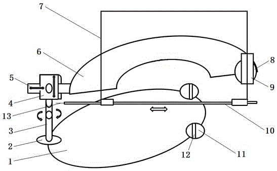
[0015] see figure 1 , a cranial locator, including a puncture point defining plane 1, a rectangular line 7 and a puncture line 13, the puncture point defining plane 1 is provided with a rotating seat 2 and a puncture point positioning ball 11; The guide groove 12 passes through the center of the sphere, so the guide groove 12 can be rotated at any angle to ensure that the puncture operation is performed on a straight line and a plane; the rotating seat 2 is installed with a mounting rod 3 that rotates left and right relative to the puncture point limiting plane 1. The rod 3 is provided with a mounting block 4 for adjusting the position up and down, the mounting block 4 is provided with a sliding rod 5 for left and right adjustment, and the sliding rod 5 is perpendicular to the mounting rod 3, and one end of the sliding rod 5 is connected to ...


PUM


Abstract

The invention discloses a cranial periphery position finder which comprises a puncture point constraining plane, a rectangular wire and a puncture wire. A rotary seat and puncture point positioning balls are arranged on the puncture point constraining plane; guide grooves which are perforated through ball centers of the puncture point positioning balls are formed in the puncture point positioning balls; a mounting rod is movably mounted on the rotary seat, a mounting block is movably arranged on the top of the mounting rod, a sliding rod is movably mounted on the mounting block and is perpendicular to the mounting rod, and an end of the sliding rod is connected with one end of a sagittal position reference surface; a rotary cushion surface is arranged at the other end of the sagittal position reference surface, the rotary cushion surface and the sagittal position reference surface are coplanar, and a bearing tube is arranged on the rotary cushion surface; a wide edge of the rectangular wire penetrates the bearing tube, a wire tube is arranged at a long edge of the rectangular wire, and the puncture wire penetrates the wire tube. The cranial periphery position finder has the advantages that the cranial periphery position finder is simple in structure, convenient to operate and high in target hit rate, the patient treatment time can be shortened, accurate puncture can be guaranteed, the treatment success rate can be increased, and popularization and application of the cranial periphery position finder primary hospitals can be facilitated.

Description

technical field [0001] The invention relates to a medical auxiliary device, in particular to a cranial locator. Background technique [0002] Stroke is the scientific name of stroke, which is a sudden onset of cerebral blood circulation disorder. The clinical manifestations are mainly characterized by sudden dizziness, unconsciousness, or sudden appearance of deviated eyes and mouth, hemiplegia, strong tongue, and intellectual disability. Cerebral stroke includes ischemic stroke (transient ischemic attack, atherosclerotic cerebral infarction, lacunar cerebral infarction, cerebral embolism), hemorrhagic stroke (cerebral hemorrhage, subarachnoid hemorrhage), high Hypertensive encephalopathy and vascular dementia are classified into four categories. [0003] Stroke is a frequently-occurring disease with high morbidity and mortality in society, and cerebral hemorrhage is the primary factor. Since the introduction of minimally invasive hematoma evacuation in 1997, cerebral hem...

Claims


Application Information

Patent Timeline
IPC IPC(8): A61B17/34
CPCA61B17/3403A61B2017/3407
Inventor 周军
Owner 周军
Learn More