Sealing structure of implanted type device and manufacturing method of sealing structure

A technology of sealing structure and manufacturing method, applied in the fields of implant stimulator, electrotherapy, medical science, etc., can solve problems such as aging, degradation, cracking, re-crosslinking, adverse biological reactions, and negative effects of implanted objects, and achieve Improved biosafety, long-term implant reliability, and improved airtight performance

Active Publication Date: 2016-02-03
SHENZHEN SIBIONICS CO LTD
View PDF6 Cites 11 Cited by
  • Summary
  • Abstract
  • Description
  • Claims
  • Application Information

AI Technical Summary

Problems solved by technology

[0003] Since implantable devices need to be implanted in the body and remain in the body for a long time, the implantable devices implanted in the body need to face the complex physiological environment in the body, which is often harsh. It may interact with surrounding tissues and organs. For example, the materials of implantable devices will undergo physical or chemical reactions such as aging, degradation, cracking, and re-crosslinking, which will have negative effects on the implanted object, such as causing adverse biological reactions such as inflammation.

Method used


Image

  • Sealing structure of implanted type device and manufacturing method of sealing structure
  • Sealing structure of implanted type device and manufacturing method of sealing structure
  • Sealing structure of implanted type device and manufacturing method of sealing structure

Examples


no. 1 approach

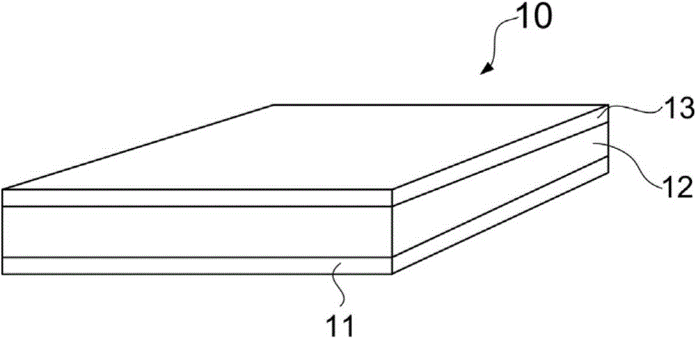
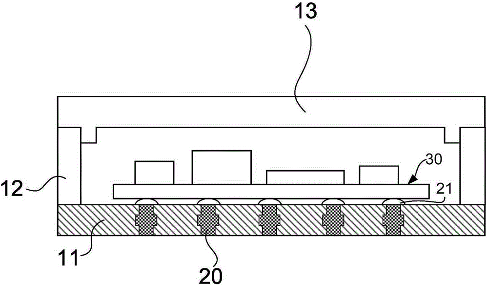
[0038] figure 1 A perspective structural view of the sealing structure 10 of the implantable device according to the first embodiment of the present invention is shown. figure 2 showfigure 1 The internal schematic diagram of the sealing structure 10 of the implantable device is shown.

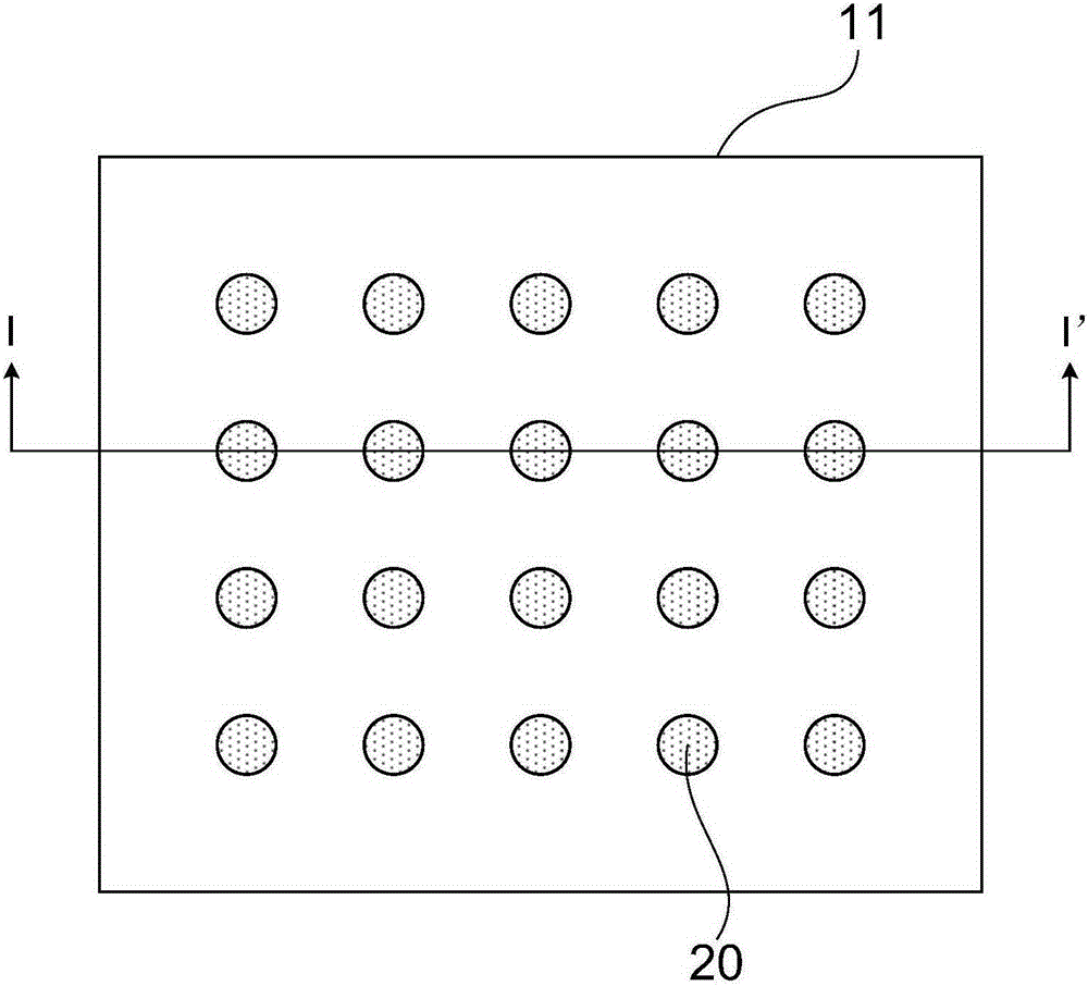
[0039] Such as figure 1 with figure 2 As shown, the sealing structure 10 of the implantable device according to the first embodiment of the present invention includes a ceramic base 11 , a metal ring 12 and a metal cover 13 . Specifically, the sealing structure 10 is formed as a sealing body having an accommodating space for accommodating the electronic component 30 by disposing (for example, welding) a metal ring 12 and a metal cover 13 on the ceramic substrate 11 .

[0040] Additionally, if figure 1 As shown, the sealing structure 10 is substantially in the shape of a cuboid. In this embodiment, the size of the sealing structure 10 of a typical implantable device is, for example, 10 mm...

no. 2 approach

[0091] Below, refer to Figure 8 , the sealing structure 101 of the implantable device according to the second embodiment of the present invention will be described.

[0092] Figure 8 A schematic cross-sectional view of the ceramic substrate 111 of the sealing structure 101 of the implantable device according to the second embodiment of the present invention is shown. For convenience of description, the sealing structure 101 here only shows the parts different from the sealing structure 10 of the implantable device related to the first embodiment. Such as Figure 8 As shown, the ceramic substrate 111 of the sealing structure 101 of the implantable device according to the second embodiment of the present invention is different from the ceramic substrate 11 of the sealing structure 10 of the implantable device according to the first embodiment of the present invention The point is that the metal post 201 in the ceramic substrate 111 is composed of a post body 201a and two po...

no. 3 approach

[0099] Below, refer to Figure 9 , the sealing structure 102 of the implantable device according to the third embodiment of the present invention will be described.

[0100] Figure 9 A schematic cross-sectional view of the ceramic substrate 112 of the sealing structure 102 of the implantable device according to the third embodiment of the present invention is shown. For convenience of description, the sealing structure 102 here only shows the parts different from the sealing structure 10 of the implantable device related to the first embodiment. Such as Figure 9 As shown, the ceramic substrate 112 of the sealing structure 102 of the implantable device according to the third embodiment of the present invention is different from the ceramic substrate 11 of the sealing structure 10 of the implantable device according to the first embodiment of the present invention The point is that the metal post 202 in the ceramic substrate 112 is composed of a post body 202a and a threade...


PUM

PropertyMeasurementUnit
thicknessaaaaaaaaaa
diameteraaaaaaaaaa
particle sizeaaaaaaaaaa

Abstract

The invention provides a sealing structure of an implanted type device and a manufacturing method of the sealing structure. The sealing structure comprises a ceramic substrate and metal pillars, wherein the ceramic substrate is provided with an upper surface and a lower surface, and one or more through holes penetrating through the upper surface and the lower surface are formed in the ceramic substrate; the through holes are filled with the metal pillars, and concave-convex structures are formed on the contact interfaces between the metal pillars and the ceramic substrate. According to the sealing structure of the implanted type device, the concave-convex structures are formed on the contact interfaces between the metal pillars and the ceramic substrate, and therefore the contact areas between the metal pillars and the ceramic substrate can be increased. Compared with through holes with radii unchanged in the prior art, by means of the sealing structure, moisture, gas or other elements can be inhibited from leaking out of the sealing structure along the contact interfaces between the metal pillars and the ceramic substrate more effectively, and therefore air-tightness of the sealing structure can be improved.

Description

technical field [0001] The invention relates to a sealing structure of an implanted device and a manufacturing method thereof. Background technique [0002] At present, implantable devices have been widely used in various aspects such as restoring body functions, improving the quality of life or saving lives. Such implantable devices include, for example, implantable cardiac pacemakers, deep brain stimulators, cochlear implants, artificial retinas, and the like. [0003] Since implantable devices need to be implanted in the body and remain in the body for a long time, the implantable devices implanted in the body need to face the complex physiological environment in the body, which is often harsh. It may interact with surrounding tissues and organs. For example, the materials of implantable devices will undergo physical or chemical reactions such as aging, degradation, cracking, and re-crosslinking, which will negatively affect the implanted object, such as causing adverse ...

Claims


Application Information

Patent Timeline
Patent Type & Authority Applications(China)
IPC IPC(8): A61F2/02A61N1/36A61N1/375
CPCA61F2/02A61N1/36046A61N1/3605A61N1/3758
Inventor 赵瑜韩明松
Owner SHENZHEN SIBIONICS CO LTD
Why Eureka
Try Eureka