Portable sinus tract deep-cavity wound adjustable negative pressure suction apparatus

A negative pressure suction device, portable technology, applied in the direction of suction devices, wound drainage devices, hypodermic injection devices, etc., can solve the problems of polluting patients and medical staff, lack of lighting devices, easy discounts on drainage tubes, etc., to protect patients and Medical personnel, convenient operation, and the effect of avoiding iatrogenic infection

Inactive Publication Date: 2016-02-03
曹瑛
View PDF5 Cites 1 Cited by
  • Summary
  • Abstract
  • Description
  • Claims
  • Application Information

AI Technical Summary

Problems solved by technology

[0009] In view of this, the technical problem to be solved by the present invention is that the switch setting on the existing drainage tube regulator is loose and easy to fall off; the plug and suction device on the liquid or gas outlet are split structures, and the protruding outlet is easily Clothes are pulled and opened, causing drainage fluid to be exposed, contaminating patients and medical staff; the fixing hole on the suction device for hanging is small and short, making it difficult to fix, causing the drainage tube to be easily discounted and increasing the workload of nurses; there is no lighting device, and power failure Later, external lighting is used, occupying the operating plane and affecting the doctor's operation

Method used


Image

  • Portable sinus tract deep-cavity wound adjustable negative pressure suction apparatus
  • Portable sinus tract deep-cavity wound adjustable negative pressure suction apparatus

Examples


Embodiment Construction

[0025] In order to make the object, technical solution and advantages of the present invention more clear, the present invention will be further described in detail below in conjunction with the examples. It should be understood that the specific embodiments described here are only used to explain the present invention, not to limit the present invention.

[0026] Attached below figure 1 , 2 and specific embodiments to further describe the application principle of the present invention.

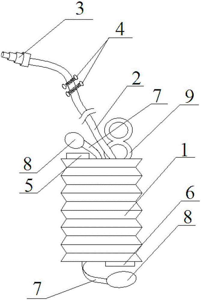
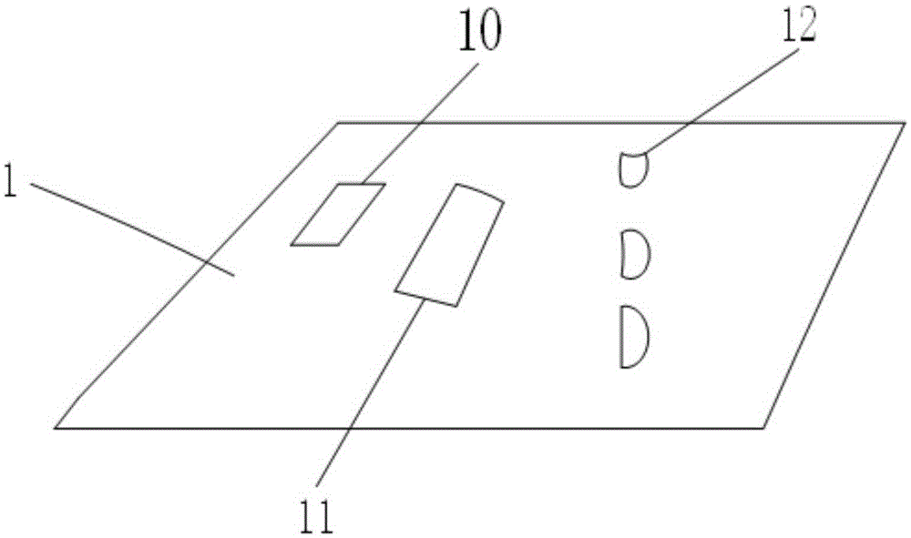
[0027] The present invention is realized like this, as figure 1 , 2 As shown, a portable adjustable negative pressure suction device for sinus deep cavity wounds includes a drainage bottle 1 with a pleated structure that can be squeezed into a vacuum state, and a drainage suction tube 2 is fixedly connected to the top of the drainage bottle 1. There is a suction nozzle 3 for detaching and removing the waste to be discharged. The suction nozzle 3 is a stepped structure with a diameter grad...


PUM

PropertyMeasurementUnit
Inner ring diameteraaaaaaaaaa

Abstract

The invention discloses a portable sinus tract deep-cavity wound adjustable negative pressure suction apparatus, which comprises a drainage tube and a drainage suction tube, wherein a plurality of switch regulating clamps are arranged on the drainage suction tube; an exhaust port is formed in the top of the drainage bottle and a drainage port is arranged at the bottom of the drainage bottle; an LED diode cold-light lamp, a control switch and a battery are arranged on the lower surface of the drainage bottle; the LED diode cold-light lamp is connected to the battery by virtue of the control switch; a connecting strap is fixedly arranged at the top of the drainage bottle and a connecting strap is fixedly arranged at the bottom of the drainage bottle; a plug which is matched with the exhaust port and a plug which is matched with the drainage port are arranged at the tail ends of the connecting straps; and an annular fixing strap is additionally arranged on the upper end face of the drainage bottle. The negative pressure suction apparatus disclosed by the invention is good in regulating property and not easy in falloff, and the plug of the exhaust port is not easy to remove, so as to effectively avoid the leakage of drainage liquid; meanwhile, the drainage liquid is convenient to be poured, and the drainage bottle is convenient to be hung; and the suction apparatus can reduce medical material consumption, guarantee a normal operation even in the case of power failure, diminish the occupied area of an operating table and reduce an infection source.

Description

technical field [0001] The invention belongs to the technical field of medical devices, in particular to a portable adjustable negative pressure suction device for sinus deep cavity wounds. Background technique [0002] Negative pressure suction is to create a negative pressure state at the suction end by a certain method, and use atmospheric pressure to squeeze the substance to be drained at the suction end to the inside of the suction end, so as to complete the effect of attracting the substance. [0003] At present, hospitals need to use negative pressure aspirators to remove the effusion in the stomach, chest cavity, and abdominal cavity, to remove blood exuded during surgery, or to remove sputum in the oral cavity and trachea. [0004] The negative pressure aspirator commonly used in traditional Chinese medicine hospital has the following disadvantages in the prior art: [0005] 1. The switch on the drainage tube regulator is a pulley-type adjustment switch on the comm...

Claims


Application Information

Patent Timeline
IPC IPC(8): A61M27/00A61M1/00
CPCA61M1/0023A61M27/00A61M1/742
Inventor 曹瑛薛耀明高方邹梦晨罗祥蓉蒋娅谢翠华
Owner 曹瑛
Why Eureka
Try Eureka