A hydraulically controlled gear transmission fixture

A hydraulic control system and tooth profile technology, applied in the field of machining, can solve problems such as machining deformation, achieve the effects of uniform pressing force, reduce clamping deformation, and improve positioning accuracy

Active Publication Date: 2018-01-19
SHENYANG LIMING AERO-ENGINE GROUP CORPORATION
View PDF6 Cites 0 Cited by
  • Summary
  • Abstract
  • Description
  • Claims
  • Application Information

AI Technical Summary

Problems solved by technology

[0003] The purpose of the invention is to solve the problem of processing deformation of easily deformed parts such as outer culvert bearing rings, and improve the processing accuracy of parts by reducing the clamping stress caused by human factors. Correct the timing of parts and improve the clamping efficiency of parts

Method used


Image

  • A hydraulically controlled gear transmission fixture
  • A hydraulically controlled gear transmission fixture
  • A hydraulically controlled gear transmission fixture

Examples


Embodiment Construction

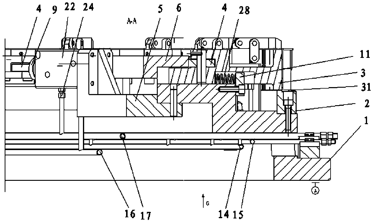
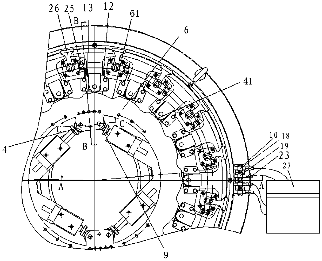
[0017] The present invention is specifically described below in conjunction with accompanying drawing, as Figure 1-Figure 4 As shown, the present invention includes a base 1, a positioning ring 2 is fixed on the base 1, and a top block 3 is automatically tightened by a hydraulic control system;

[0018] Described hydraulic control system comprises basic type double-action cylinder 22, pulley 4, cam 6, the piston of basic type double-action cylinder 22 pushes support block 9, and support block 9 promotes pulley-4 to drive cam 6 to rotate, and the notch of cam 6 61 abuts against the second pulley 41, and the second pulley 41 is in axial contact with the rotating shaft on the top block 3;

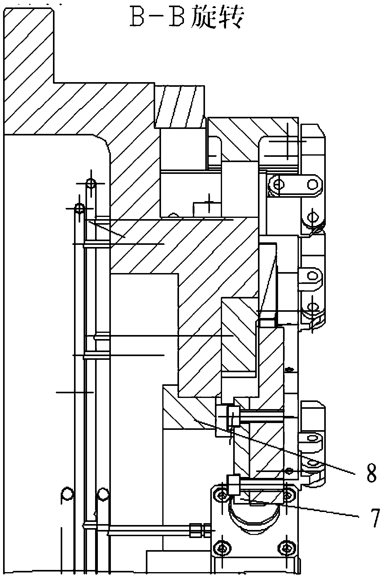
[0019] The cam 6 is formed by the rotating stage 8, the patch plate 7, the stopper 11 and the base 1 to form a guide mechanism that takes the center of the circle as the rotating shaft and slides along the circumference. The compression spring is fixed between the baffle plate 11 and the top ...


PUM


Abstract

The invention discloses a hydraulic control tooth type transmission clamp. The clamp comprises a base; a positioning ring is fixed to the base; an ejecting block is automatically expanded through a hydraulic control system; the hydraulic control system comprises a basic double-action cylinder, a first pulley and a cam; a piston of the basic double-action cylinder pushes a supporting block; the supporting block pushes the first pulley to drive the cam to rotate; a notch of the cam is connected with a second pulley in an abutting manner; and the second pulley is connected with a rotating shaft on the ejecting block through a shaft. The clamp further comprises linear pressing plate oil cylinders uniformly distributed along the circumference of a workpiece; oil inlet and outlet pipe pressing plate oil cylinder pressing oil pipes and pressing plate releasing oil pipes of the linear pressing plate oil cylinders are installed at the bottom of the base; and energy accumulators for pressure compensation are installed on the oil inlet and outlet pipe pressing plate oil cylinder pressing oil pipes, and the part pressing process is completed through pressure adjustment. The hydraulic control tooth type transmission clamp has the beneficial effects that a hydraulic control tool is adopted to guarantee gapless positioning of a part, the positioning precision of the part is improved, a hydraulic clamping mechanism can guarantee that the pressing force of the part is uniform, clamping deformation of the part is reduced, and the machining precision of the part is ensured.

Description

technical field [0001] The invention relates to the field of mechanical processing, in particular to a hydraulic transmission clamp. Background technique [0002] The structure of casing parts is complex and requires high machining accuracy. Since most of the parts are thin-walled structures, the clamping and processing deformation of the parts is large. The ordinary mechanical positioning and clamping mechanism cannot guarantee gap-free positioning and uniform compression, resulting in parts positioning. The precision is low, and the clamping deformation of the parts is large. Contents of the invention [0003] The purpose of the invention is to solve the problem of processing deformation of easily deformable parts such as outer culvert bearing rings, and improve the processing accuracy of parts by reducing the clamping stress caused by human factors. Correct the timing of parts and improve the clamping efficiency of parts. The specific technical scheme is as follows: ...

Claims


Application Information

Patent Timeline
Patent Type & Authority Patents(China)
IPC IPC(8): B23Q3/08
CPCB23Q3/065B23Q3/082
Inventor 张娟彭会文阚敏曾庆国马镇镇
Owner SHENYANG LIMING AERO-ENGINE GROUP CORPORATION
Why Eureka
Try Eureka