
A stirring and feeding mechanism

A technology of feeding mechanism and stirring mechanism, which is used in stirring devices, lighting and heating equipment, furnace components, etc., can solve the problems of affecting the quality of the solution, affecting the effect of deterioration, and insufficient dissolution of the added material, and achieves stable experimental data and elements. The effect of uniform distribution and guaranteed stability

Active Publication Date: 2018-02-02
YINBANG CLAD MATERIAL
View PDF8 Cites 0 Cited by
  • Summary
  • Abstract
  • Description
  • Claims
  • Application Information

AI Technical Summary

Problems solved by technology

[0002] When the laboratory uses an ordinary crucible resistance furnace to smelt aluminum alloy, it is difficult to simulate the industrial production site, and many problems will be encountered during the experiment:
[0003] 1. Ordinary crucible resistance furnaces do not have a stirring device, and manual stirring or other mixers are needed, which is difficult to ensure that the alloying elements are evenly distributed in the melt and ensure the quality of the melt;
[0004] 2. Ordinary crucible resistance furnaces are not equipped with feeding devices. When adding metals or powdered refining agents and sodium salt modifiers that are lighter than aluminum liquids into the aluminum liquid, it is necessary to manually press them into the aluminum liquid with special equipment, resulting in Insufficient dissolution of the added materials and severe burning loss will affect the quality of the solution, especially when sodium salt modifier is added, the sodium salt is easy to stick to the bell jar, thus affecting the effect of modification

Method used


Image

  • A stirring and feeding mechanism
  • A stirring and feeding mechanism
  • A stirring and feeding mechanism

Examples


Embodiment Construction

[0034] Specific embodiments of the present invention will be described in detail below in conjunction with the accompanying drawings.

[0035] The examples described here are specific specific implementations of the present invention, and are used to illustrate the concept of the present invention. They are all explanatory and exemplary, and should not be construed as limiting the implementation of the present invention and the scope of the present invention. In addition to the embodiments described here, those skilled in the art can also adopt other obvious technical solutions based on the claims of the application and the contents disclosed in the description, and these technical solutions include adopting any obvious changes made to the embodiments described here. The replacement and modified technical solutions are all within the protection scope of the present invention.

[0036] The accompanying drawings in this specification are schematic diagrams, which assist in expla...


PUM


Abstract

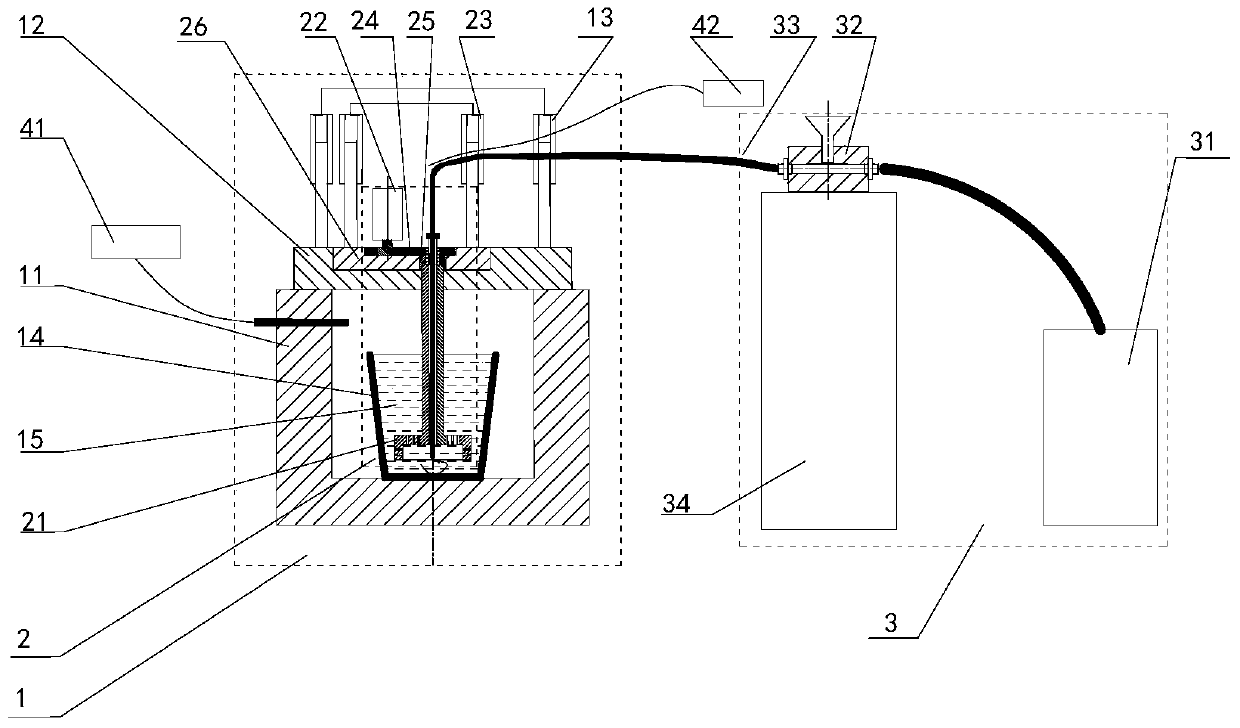
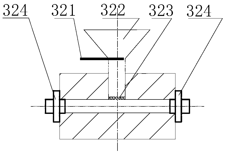
The invention provides a stirring and conveying mechanism. A stirring mechanism penetrates through a furnace lid from the interior of a furnace chamber, extends outside and is supported outside on a mounting plate on the furnace lid; outside the furnace chamber, a transmission system and a second hydraulic cylinder are connected between the mounting plate and the stirring mechanism and are used for providing rotating and stretching power for the stirring mechanism respectively; a conveying mechanism comprises an air compressor, a feeding tank, a conveying pipe and a support seat; the support seat is located below the feeding tank and is used for supporting and fixing the feeding tank; two ends of the feeding tank are connected with the air compressor and the conveying pipe through connectors respectively; and the tail end of the conveying pipe is communicated with a center through hole of a graphite bell jar for a molten metal stirrer. Through the design and use of the structure, the stability of ingot quality can be guaranteed, so that the stability and reliability of later-period experiment data are guaranteed.

Description

technical field [0001] The invention relates to the field of metal smelting, in particular to a stirring and feeding mechanism for an aluminum alloy smelting device. Background technique [0002] When the laboratory uses an ordinary crucible resistance furnace to smelt aluminum alloy, it is difficult to simulate the industrial production site, and many problems will be encountered during the experiment: [0003] 1. Ordinary crucible resistance furnaces do not have a stirring device, and manual stirring or other mixers are needed, which is difficult to ensure that the alloying elements are evenly distributed in the melt and ensure the quality of the melt; [0004] 2. Ordinary crucible resistance furnaces are not equipped with feeding devices. When adding metals or powdery refining agents and sodium salt modifiers that are lighter than aluminum liquids into the aluminum liquid, it is necessary to manually press them into the aluminum liquid with special equipment, resulting in...

Claims


Application Information

Patent Timeline
Patent Type & Authority Patents(China)
IPC IPC(8): F27D27/00F27D3/18F27B14/16F27B14/20C22C1/06C22C21/00
Inventor 仲召军李龙周德敬
Owner YINBANG CLAD MATERIAL
Learn More