Nanofiber Parallel Tensile Testing System and Method

A nanofiber and tensile testing technology, applied in the field of micro-nano technology, can solve the problems of uncontrollable error and large error of Young's modulus

Inactive Publication Date: 2018-04-27
SHANGHAI UNIV
View PDF9 Cites 0 Cited by
  • Summary
  • Abstract
  • Description
  • Claims
  • Application Information

AI Technical Summary

Problems solved by technology

[0004] In order to overcome the shortcomings of the above-mentioned prior art, the present invention provides a nanofiber parallel tensile testing system and method, which solves the problem that the existing experimental system and method obtain Young's modulus with large errors and uncontrollable errors

Method used


Image

  • Nanofiber Parallel Tensile Testing System and Method
  • Nanofiber Parallel Tensile Testing System and Method
  • Nanofiber Parallel Tensile Testing System and Method

Examples


Embodiment 1

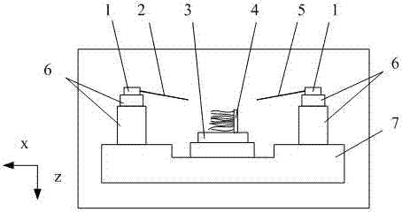
[0041] see figure 1 and figure 2 , the nanofiber parallel tensile testing system includes an electron microscope connected parallel tensile testing system, characterized in that: the electron microscope uses its excellent imaging capability to provide image data and operation basis for the parallel tensile testing system; the parallel The tensile test system includes a workbench (7), two closed-loop fast-feed mechanisms (6), two closed-loop fine-feed mechanisms (1), flexible probe sets (2), rigid probe sets (5), nanofiber culture dish (4), sample workbench (3); the two closed-loop rapid feed mechanisms (6) are installed on the left and right sides of the workbench (7) respectively, and the two closed-loop precision feed mechanisms (1) are respectively installed on the two on a closed-loop fast-feed mechanism (6); the flexible probe group (2) and the rigid probe group (5) are respectively installed on the closed-loop fine-feed mechanism (1) on the left and right sides; the na...

Embodiment 2

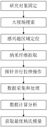
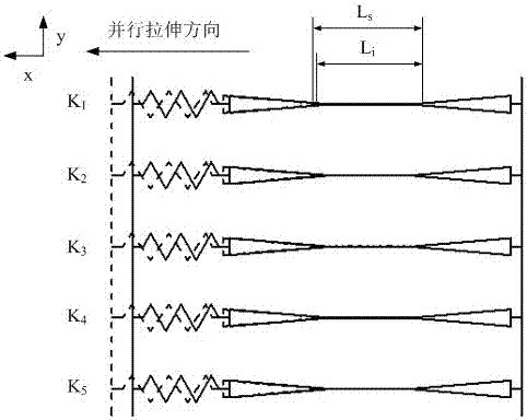
[0043] see figure 1 , image 3 and Figure 4 , this nanofiber parallel tensile test method, adopts above-mentioned system to carry out parallel tensile test, operation steps are as follows:

[0044] Step 1: Fix the research object: fix the nanofiber culture dish (4) on the sample workbench (3), push the sample workbench (3) into the electron microscope chamber for follow-up work;

[0045] Step 2: Large field of view search: use the large field of view search capability of the electron microscope to determine the position of the nanofiber on the sample workbench (3), and focus the research object until it is clearly visible;

[0046] Step 3: Locate the region of interest: move the sample worktable (3) to determine the region of interest on the research object, increase the magnification and focus on the nanofiber of interest;

[0047] Step 4: Picking up nanofibers: calibrate the region of interest according to the global position coordinates, use the parallel stretching syst...


PUM


Abstract

The invention discloses a nano fiber parallel tensile testing system and method. The system comprises an electron microscope which is connected with a parallel tensile testing system; the parallel tensile testing system is used for carrying out pickup and parallel tensile operation on nano fibers and obtaining a Young modulus with controllable nano fiber errors through controlling an error range of influence factors of each link, and acquiring, processing and calculating data. The method comprises the following steps: firstly, carrying out operation on the nano fibers, including research object fixation, large-view-field searching, area-of-interest positioning, nano fiber pickup, and probe parallel tensile operation; then, acquiring analysis data by using the electron microscope and a micro-force sensor and acquiring the Young modulus with a controllable error range through calculating and analyzing the data. The embodiment of the invention is mainly used for acquiring the Young modulus of the nano fibers and the nano fibers are operated through the parallel tensile testing system; the controllable Young modulus of the nano fibers is acquired through controlling error sizes of the influence factors of each link.

Description

technical field [0001] The invention discloses a nanofiber parallel tensile testing system and method, and relates to the fields of micro-nano technology and micro-nano operation. Background technique [0002] Semiconductor nanofiber materials have unique physical and chemical properties, and have potential application advantages in electronic devices, optical devices, etc. The research on the properties of nanofibers, especially the determination of Young's modulus, has certain guiding significance and reference value for the macroscopic mechanical properties of bulk materials, especially the newly synthesized bulk materials with unknown mechanical properties. Research methods to explore the properties of nanofibers play an important role in promoting the continuous development of material characterization methods and experimental methods. [0003] At present, there are many methods for measuring the Young's modulus of nanofibers. The main method is to measure multiple nan...

Claims


Application Information

Patent Timeline
Patent Type & Authority Patents(China)
IPC IPC(8): G01N3/06
Inventor 曹宁谢少荣罗均李恒宇龚振邦
Owner SHANGHAI UNIV
Why Eureka
Try Eureka