Resonant charging nanosecond leading edge pulse current generator

A technology of pulse current and resonant charging, applied in the direction of electric pulse generator circuit, etc., can solve the problems of bulky, complex structure, unfavorable device promotion and application, etc., and achieve the effect of high insulation level, convenient connection and compact structure

Active Publication Date: 2016-02-03
NORTHWEST INST OF NUCLEAR TECH +1
View PDF6 Cites 11 Cited by
  • Summary
  • Abstract
  • Description
  • Claims
  • Application Information

AI Technical Summary

Problems solved by technology

[0004] At present, the shunt method used to generate the pre-pulse current is particularly dependent on the parallel bypass load, which has a complex structure and a large volume, which is not conducive to the popularization and application of the device.

Method used


Image

  • Resonant charging nanosecond leading edge pulse current generator
  • Resonant charging nanosecond leading edge pulse current generator
  • Resonant charging nanosecond leading edge pulse current generator

Examples


Embodiment Construction

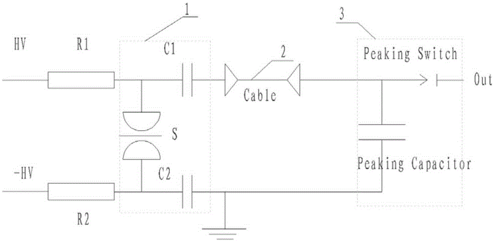
[0024] see figure 1 , The preferred embodiment of the present invention is composed of a charging branch 1, a charging cable 2 and a peaking circuit 3, and the peaking circuit 3 is composed of a peaking capacitor and a peaking switch. The charging branch 1 resonantly charges the peaking capacitor through the charging cable 2. When the voltage is charged to a certain value, the peaking switch is closed and can output tens of nanoseconds of fast leading edge pulse current.

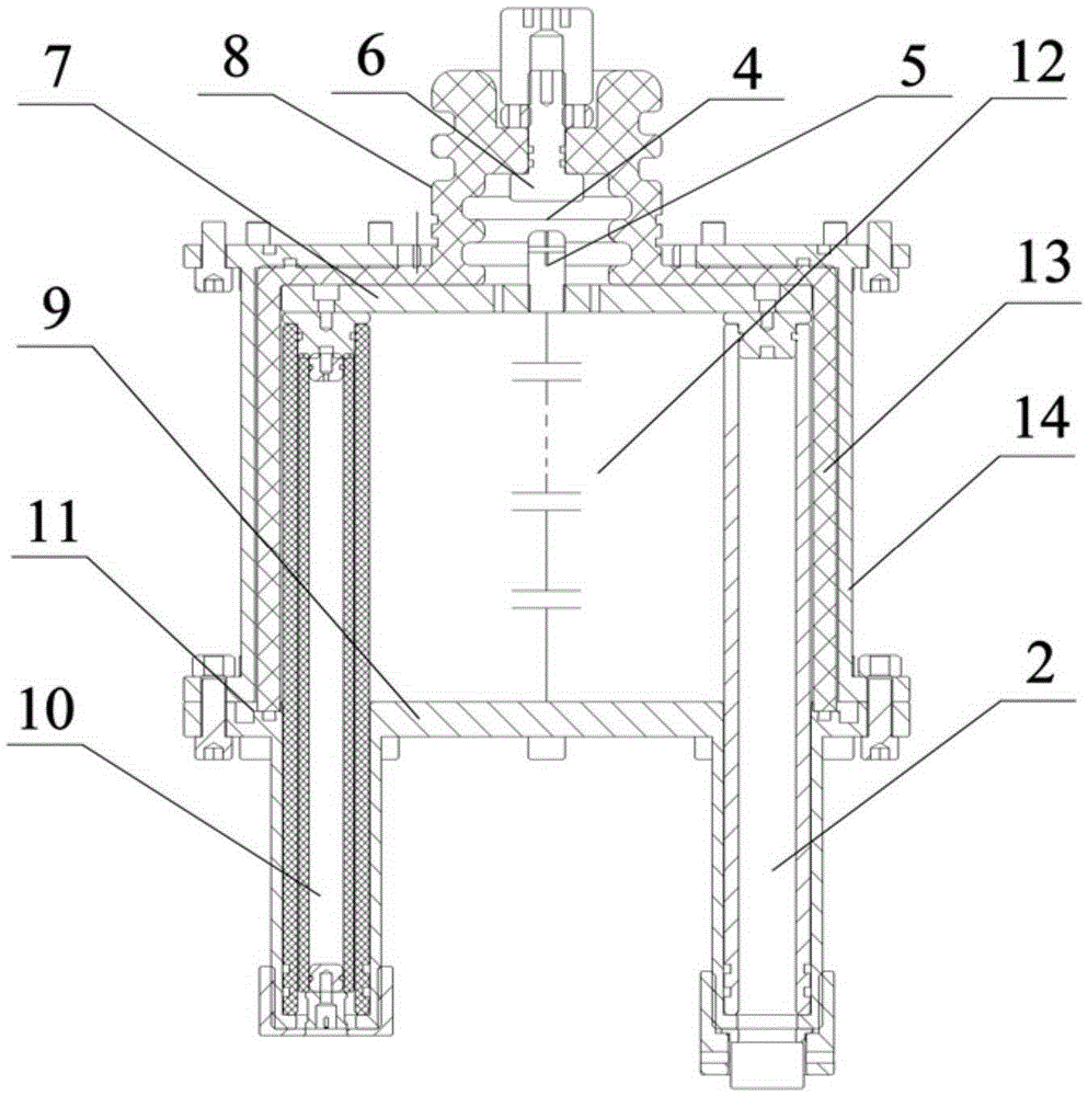
[0025] see figure 2 , The peaking capacitor 12 of the preferred embodiment of the present invention is a low-inductance capacitor composed of a plurality of thin-film capacitive elements connected in series. Changing the number of elements connected in series can change the capacitor capacity and withstand operating voltage. The upper end of the peaking capacitor 12 is a high-voltage electrode plate 7 , the lower end is a ground electrode plate 9 , and an insulating shell 13 and a metal shell 14 are arrang...


PUM


Abstract

The invention relates to a resonant charging nanosecond leading edge pulse current generator, comprising a charging branch, a charging cable and a peaking loop. The peaking loop comprises a peaking switch and a peaking capacitor. One end of the peaking capacitor is a grounded electrode plate, and the other end thereof is a high voltage electrode plate. The high voltage electrode plate and the high voltage electrode end of the peaking switch are connected into a whole, and the other end of the peaking switch is a pulse source output electrode. The high voltage electrode plate of the peaking capacitor is connected with the charging branch through the charging cable. An insulation shell is arranged outside the peaking capacitor. The insulation shell and the grounded electrode plate and the high voltage electrode plate of the peaking capacitor jointly define a sealed cavity filled with a gas medium. The high-amplitude pulse current generator has a compact structure and a small volume, adopts a resonant charging manner, is adjustable in output polarity, and can generate tens of nanoseconds of fast leading edge high-amplitude pulse current in a low resistance load condition.

Description

technical field [0001] The invention relates to a nanosecond front edge pulse current generator. Background technique [0002] The Z pinch generated by pulsed large current passing through the wire array load has important application requirements in weapon physics, X-ray radiation effect research, fusion energy, etc., such as the US ZR device (26MA), the Chinese Academy of Engineering Physics Julong No. )Wait. [0003] Research on the MAGPIE device by Imperial College London shows that the Z-pinch wire array first passes through a pre-pulse current of tens of nanoseconds, heats and gasifies, and forms a symmetrical and uniform thin-layer cylindrical metal gas, and then passes through the main pulse after a certain time delay High current can suppress the development of instability, which is beneficial to improve the X-ray power of Z-pinch radiation. The pre-pulse current of the MAGPIE device is shunted through the bypass load. After a certain time delay, the bypass load i...

Claims


Application Information

Patent Timeline
Patent Type & Authority Applications(China)
IPC IPC(8): H03K3/02
Inventor 孙凤举王志国姜晓峰邱爱慈梁天学李兴文吴坚
Owner NORTHWEST INST OF NUCLEAR TECH
Why Eureka
Try Eureka