
Method for realizing microgrid control system based on high-speed Ethernet industrial bus

An industrial bus and control system technology, applied in the field of micro-grid system, to achieve the effect of easy engineering implementation, conducive to expanding application, and improving data transmission speed

Inactive Publication Date: 2016-02-03
BEIJING DEYI XINNENG ELECTRICAL CO LTD
View PDF3 Cites 1 Cited by
  • Summary
  • Abstract
  • Description
  • Claims
  • Application Information

AI Technical Summary

Problems solved by technology

[0007] In order to solve the problems of various communication methods in the current micro-grid system, and at the same time enable faster and real-time information interaction between distributed power sources, measurement and control equipment, loads, and micro-grid monitoring platforms to ensure stable control of the micro-grid system, The invention provides a method for implementing a micro-grid control system based on a high-speed Ethernet industrial bus. All components in a micro-grid system such as distributed power supplies, measurement and control equipment, loads, and micro-grid monitoring platforms are passed through a unified EtherCAT industrial bus in a specific order. The communication connection avoids the inconsistency of traditional ModbusRTU, ModbusTCP and other communication methods. At the same time, through the EtherCAT industrial bus, the information interaction between distributed power supply, measurement and control equipment, load and micro-grid monitoring platform is realized. The communication speed is fast. Significantly improved, it is helpful to realize the coordinated control of the microgrid system

Method used


Image

  • Method for realizing microgrid control system based on high-speed Ethernet industrial bus
  • Method for realizing microgrid control system based on high-speed Ethernet industrial bus
  • Method for realizing microgrid control system based on high-speed Ethernet industrial bus

Examples


Embodiment Construction

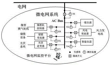
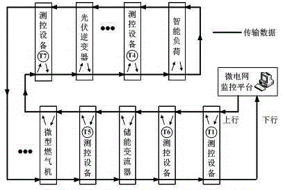
[0027] An implementation method of a micro-grid control system based on a high-speed Ethernet industrial bus of the present invention is suitable for a typical micro-grid system composed of distributed power sources, measurement and control equipment, loads, and micro-grid monitoring systems, among which distributed power sources, measurement and control equipment, etc. Information exchange is realized through the EtherCAT industrial bus, and the status of the grid-connected point voltage, current, and isolating switch of the micro-grid system can be transmitted to the distributed power supply and other equipment more quickly according to a specific connection sequence, so as to realize the multi-objective and stable operation of the micro-grid system.

[0028] A method for implementing a micro-grid control system based on a high-speed Ethernet industrial bus in the present invention will figure 1 The distributed power supply, measurement and control equipment, load and microg...


PUM


Abstract

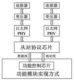
The invention provides a method for realizing a microgrid control system based on a high-speed Ethernet industrial bus, which is applicable to a typical microgrid system composed of a distributed power supply, a load and a microgrid monitoring platform. In the microgrid system, the distributed power supply, the load and the microgrid monitoring platform are connected by a unified EtherCAT industrial bus, wherein one device is a master station, and the other devices are slave stations, and data transmission can be realized between the master station and the slave stations and between the slave stations through the EtherCAT bus. As shown in Fig.1, the distributed power supply, the load and the microgrid monitoring platform are connected according to a specific sequence to transmit voltage, current and other analog quantity information and a switch command, state feedback and other digital quantity information in the microgrid system to the distributed power supply and other devices more quickly, so as to meet the control demands of grid connected and isolated island switch of the microgrid system, and extensive application and engineering implementation are better facilitated on the basis of guaranteeing the data transmission instantaneity.

Description

Technical field [0001] The patent of the present invention relates to the field of micro-grid systems, and specifically relates to the use of a unified EtherCAT industrial bus in the micro-grid system to realize information interaction between distributed power sources and between distributed power sources and the central control system, improve data transmission speed, and improve micro-grid The ability to connect the system to the grid, operate stably in an isolated island, and switch between different modes. Background technique [0002] At present, my country is vigorously building the smart grid business. As an important part of the smart grid, the micro-grid system can effectively solve the contradiction between the large power grid and the intermittent distributed power supply, and has received extensive attention and development. The microgrid system can be regarded as a distribution subnetwork including local distributed power sources and loads in the power system. ...

Claims


Application Information

Patent Timeline
IPC IPC(8): H04L12/42H04L29/08H02J13/00
CPCY02B90/20Y04S40/124
Inventor 梁建钢王申平耿欢刘凯
Owner BEIJING DEYI XINNENG ELECTRICAL CO LTD
Learn More