
Automatic chip mounting production line

An automatic patch and assembly line technology, applied in electrical components, electrical components and other directions, can solve the problems of deviation of dispensing position detection effect, affecting process processing, access and other problems, and achieve high dispensing accuracy, simple structure and high efficiency.

Inactive Publication Date: 2016-02-03
JIANGSU HAITIAN MICROELECTRONICS TECH
View PDF5 Cites 6 Cited by
  • Summary
  • Abstract
  • Description
  • Claims
  • Application Information

AI Technical Summary

Problems solved by technology

[0003] In the actual operation and use process, affected by the position of the conveyor belt and the dispensing head, the actual dispensing effect will have a large discrepancy, and there is a certain deviation in the dispensing position. Influenced by factors such as distance, the actual CCD detection effect will have a large discrepancy, and there is also a certain deviation in the detection effect of the dispensing position, which directly affects the subsequent process processing

Method used


Image

  • Automatic chip mounting production line
  • Automatic chip mounting production line
  • Automatic chip mounting production line

Examples


Embodiment Construction

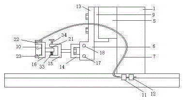
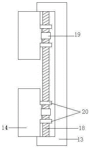
[0021] An automatic patch assembly line as shown in the figure includes a feeding station 101, a glue dispensing station 102, a CCD detection station 103, a patch station 104 and a discharging station 105. It is characterized in that it includes a bracket 1 , the dispensing device 3 on the conveyor belt 2, the dispensing station 102 and the CCD detection device 4 on the CCD detection station 103, the dispensing device 3 includes a displacement platform 5, a fixing mechanism 6 fixed on the displacement platform 5 and The dispensing mechanism 7 fixed on the fixing mechanism 6, the conveyor belt 2 is arranged under the support 1, side plates 8 are arranged on both sides of the conveyor belt 2, and the displacement table 5 is vertically arranged on the support 1, and realizes up and down displacement , the displacement platform 5 includes a displacement end 9, the dispensing mechanism 7 includes a rubber storage tube 10, a solenoid valve 11 and a pressure regulating valve 12, and t...


PUM


Abstract

The invention provides an automatic chip mounting production line, including a loading station, a dispensing station, a CCD detection station, a chip mounting station and a discharging station. The automatic chip mounting production line is characterized in that the production line includes a support, a conveyor belt, a dispensing device and a CCD detection device, a fixed mechanism and a dispensing mechanism are arranged on the dispensing device, a lead screw and adjusting bolts are arranged on the fixed mechanism, the CCD detection device includes a two-dimensional mechanical arm, a linear telescopic cylinder and a CCD, and the CCD is equipped with an annular light source and distance sensors. The automatic chip mounting production line provided by the invention is simple in structure and reasonable in design, rapidly completes dispensing of a plurality of workpieces, and is high in efficiency, the dispensing mechanism performs fine adjustment through adjustment of the lead screw and the adjusting bolts, thereby improving dispensing precision, displacement of the CCD in a horizontal direction is realized through the two-dimensional mechanical arm, so that dispensing parts are detected, displacement precision is high, the distance sensors detect and monitor photographing distance of the CCD, and realize vertical displacement through the cylinder, selection of optimal photographing distance is facilitated, and the annular light source provides a light source for the CCD.

Description

technical field [0001] The invention relates to an automatic patch assembly line. Background technique [0002] The automatic placement machine assembly line refers to a flow-type operation platform that integrates all steps of the placement operation, including steps such as feeding, dispensing, CCD detection, and placement. The placement machine is used to achieve high-speed, high-precision full-scale The equipment that automatically places components is the most critical and complex equipment in the entire SMT production. The placement machine is the main equipment in the SMT production line. The placement machine has developed from an early low-speed mechanical placement machine to a high-speed optical centering placement machine, and has developed into a multi-functional, flexible connection modularization. [0003] In the actual operation and use process, affected by the position of the conveyor belt and the dispensing head, the actual dispensing effect will have a la...

Claims


Application Information

Patent Timeline
Patent Type & Authority Applications(China)
IPC IPC(8): H05K13/04
Inventor 李霖
Owner JIANGSU HAITIAN MICROELECTRONICS TECH
Learn More