
Method for eliminating flow field vortexes in tubular electrode electrolytic machining interval

A technology of machining gap and internal flow field, applied in electric machining equipment, electrochemical machining equipment, machining electrodes, etc., can solve the problems of affecting machining accuracy, deteriorating machining environment, reducing the stability of machining process, etc., and reducing short circuit in machining process. , the effect of improving process stability

Inactive Publication Date: 2016-02-10
SHANDONG UNIV OF TECH
View PDF6 Cites 24 Cited by
  • Summary
  • Abstract
  • Description
  • Claims
  • Application Information

AI Technical Summary

Problems solved by technology

However, the electrolyte in the eddy current area is difficult to update in time, and it is easy to form a "dead water area". It also destroys the balance of electrolyte pressure in the machining gap, causing the tube electrode to vibrate, which also increases the probability of short circuit, reduces the stability of the machining process, and affects the machining accuracy.

Method used


Image

  • Method for eliminating flow field vortexes in tubular electrode electrolytic machining interval
  • Method for eliminating flow field vortexes in tubular electrode electrolytic machining interval
  • Method for eliminating flow field vortexes in tubular electrode electrolytic machining interval

Examples


Embodiment Construction

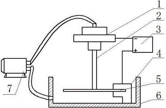
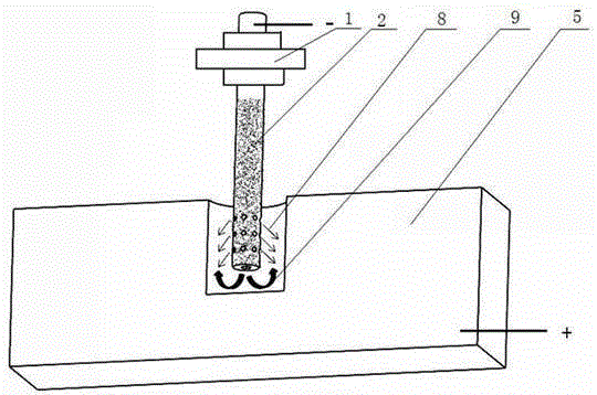
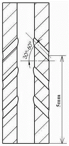
[0016] Such as figure 1 The schematic diagram of the setup for electrolytic machining of tube electrodes and figure 2 The schematic diagram of the processing area of ​​the tube electrode electrolytic machining is shown, which includes: the clamping and sealing device 1 of the electrolytic machining machine tool, which is responsible for clamping the tube electrode and sealing the electrolyte; Connect the clamping and sealing device 1 of the electrolytic machining machine tool, and connect the negative pole of the processing power supply as the cathode of the electrolytic machining, and spray the electrolyte downward during processing; the processing power supply 3 provides the required DC power during processing; the workpiece fixture 4 is responsible for clamping and fixing The workpiece; the workpiece 5 is connected to the positive electrode of the processing power supply 3 as the anode of the electrolytic processing; the electrolytic cell 6 provides the electrolyte proces...


PUM


Abstract

The invention provides a method for eliminating flow field vortexes in a tubular electrode electrolytic machining interval. The method comprises the following steps that the lateral face of a tubular electrode is punched through a laser punching process; the punched tubular electrode is subjected to corresponding insulating treatment; electrolyte flows downwards in the tubular electrode during electrolytic machining and is sprayed outwards from an outlet in the lower end of the tubular electrode; the electrolyte beam sprayed out of the outlet of the tubular electrode impacts an electrolytic machining area; part of electrolyte is sprayed out of a hole in the lateral face of the tubular electrode; under the impact and disturbance function of the electrolyte sprayed out of the hole in the lateral face, a vortex area of the electrolyte of the machining area is eliminated, and electrolysate is discharged out of the machining area in time in the circular flowing of the electrolyte; and meanwhile, under the function of reactive force when the electrolyte impacts, the amplitude of vibration of the tubular electrode caused by flowing of the electrolyte is reduced. The occurrence of short circuit in the machining process can be effectively reduced by eliminating the electrolysate discharged out of the vortex area and reducing the amplitude of vibration of the tubular electrode, and the process stability of the electrolytic machining of the tubular electrode is improved.

Description

technical field [0001] The invention belongs to the technical field of electrolytic machining of tube electrodes, in particular to a method for eliminating eddy currents in a flow field in gaps of electrolytic machining of tube electrodes. Background technique [0002] Tube electrode electrolytic machining is a processing technology that uses a hollow metal tube as the cathode of the tool to electrochemically etch the anode of the workpiece. It is often used for electrolytic drilling, and its application is mainly reflected in the field of aviation manufacturing. With the advancement of modern aviation industry technology, the temperature before the turbine of the aero-engine continues to increase, and the hot-end parts of the engine (such as high-pressure turbine working blades, guide vanes, combustion chambers, etc.) have widely used film cooling technology, and each blade has dozens of There are tens of thousands of such film cooling holes in the combustion chamber. Thes...

Claims


Application Information

Patent Timeline
Patent Type & Authority Applications(China)
IPC IPC(8): B23H3/04B23H3/00B23K26/382
CPCB23H3/00B23H3/04
Inventor 李志永路文文臧传武王钦强聂云聪崔庆伟
Owner SHANDONG UNIV OF TECH
Learn More