Measuring upper pin special machine for automobile belt tensioner

A tensioner and belt technology, applied in the field of measuring and selling special machines, can solve the problems of increasing worker fatigue, product scrapping rate, increasing unqualified products, unstable related dimensions, etc., so as to reduce scrapping rate, improve production efficiency, Simple and compact structure

Active Publication Date: 2017-10-31
WUXI YONGKAIDA GEAR
View PDF6 Cites 0 Cited by
  • Summary
  • Abstract
  • Description
  • Claims
  • Application Information

AI Technical Summary

Problems solved by technology

[0003] There are several major deficiencies in the above process: 1. The state of the product during the measurement is that the pins have been assembled, which is inconsistent with the use state of the product when it is installed on the car engine (the use state is that the tension arm in the product is at a certain angle to the housing. ), will cause the relative dimensional instability that needs to be guaranteed
2. There is no means to directly inspect the height of the pulley assembly, and only indirect inspection can be carried out on the basis of the go-no-go gauge
(The pulley assembly is press-fitted from the same two pieces together with the bearings. There are many types of single-piece pulleys, and there is a possibility of mixed pressure.) 3. When installing the pulley, it is easy to install the pulley in reverse (some pulley assemblies are installed after installation) The dust cover needs to be covered, and the pulley assembly only has a slot for installing the dust cover on one side), which increases the fatigue of workers and the scrap rate of products
4. Process measurement after other processes will lead to an increase in unqualified products, reducing benefits and wasting productivity
5. Each process needs to be transferred and transported, which increases the workload, affects the production efficiency and increases the production cost

Method used


Image

  • Measuring upper pin special machine for automobile belt tensioner
  • Measuring upper pin special machine for automobile belt tensioner
  • Measuring upper pin special machine for automobile belt tensioner

Examples


Embodiment Construction

[0019] The specific implementation manners of the present invention will be further described in detail below in conjunction with the accompanying drawings.

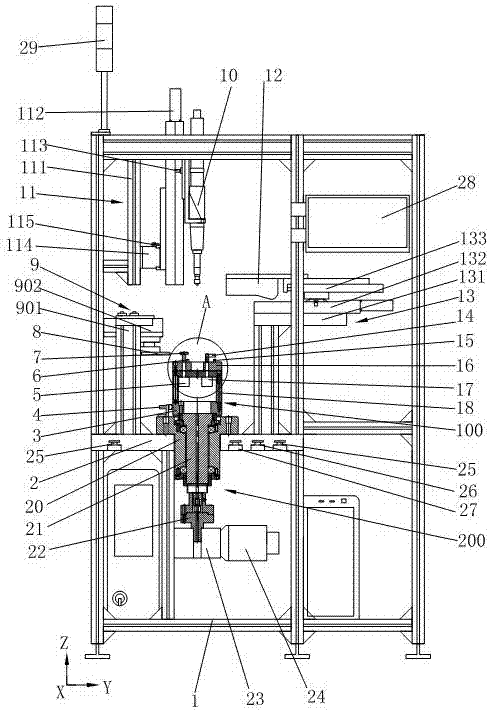
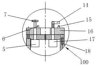
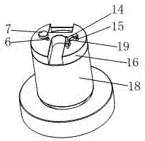
[0020] Such as figure 1 , 2 , 3, the present invention includes a frame 1 and a workbench 2, the workbench 2 is horizontally arranged on the frame 1, the swivel seat 3 is arranged on the top of the workbench 2, and the swivel seat 3 is connected to the motor drive set under the workbench 2 Agency 200. The motor drive mechanism 200 includes a bearing block 20 fixedly connected to the workbench 2. The axis of the bearing block 20 is perpendicular to the workbench 2. The main shaft 21 is rotatably installed in the bearing block 20 through the bearing. The upper end of the main shaft 21 is connected to the rotating seat 3. The main shaft 21 The lower end of the shaft coupling 22 is connected to the reducer 23 and the motor 24. The motor 24 is connected to the reducer 23 and drives the rotating base 3 to rotate through the ...


PUM


Abstract

The invention relates to a measuring and pin mounting machine of an automobile belt tensioner. The measuring and pin mounting machine is characterized in that a rotating seat is connected with a motor drive mechanism; a workpiece locating seat is coaxially arranged on the rotating seat, and comprises a seat tube and a locating plate; two compaction air cylinders are arranged in the seat tube; a first locating pin and a second locating pin are arranged on the locating plate; a circular pressing plate and a V-shaped pressing plate are respectively connected with the piston rods of the compaction air cylinders; a movable baffle block is arranged on one side of the workpiece locating seat, and a movable 3D intelligent measurement sensor is arranged on the other side of the workpiece locating seat; a two-way movement mechanism is arranged above the workpiece locating seat; and a tightening gun is connected with the two-way movement mechanism. According to the measuring and pin mounting machine, the structure is simple and compact, and the belt pulley mounting, size measurement and pin mounting are achieved in a single process, so that the automation level is improved, the production efficiency is improved, the qualification rate of the product is increased, and the production cost is reduced.

Description

technical field [0001] The invention relates to a special device, in particular to a special machine for measuring upper pins of an automobile belt tensioner. Background technique [0002] When assembling the belt tensioner of an automobile engine, the commonly used process is to first screw the tension arm and the shell together (press riveting), and then put the pin (after rotating the tension arm and the shell to form a certain angle) , insert the assembly pin), and then use the CNC milling machine to mill out the pulley installation surface (the drawing has strict requirements on the height and parallelism from the tensioner installation reference surface (shell bottom) to the pulley installation surface, so it is necessary to mill out the blank margin to the required size, and the parallelism can also be guaranteed by milling), then install the pulley, and finally measure (the measurement here can only be carried out by using a go-no-go gauge because the pulley is insta...

Claims


Application Information

Patent Timeline
Patent Type & Authority Patents(China)
IPC IPC(8): B23P21/00G01B21/02G01B21/10
CPCB23P21/006B23P2700/50G01B21/02G01B21/10
Inventor 糜建鸿虞晓彬
Owner WUXI YONGKAIDA GEAR
Why Eureka
Try Eureka