An air source flexible gas heat pump unit and its operating method

A gas-fired heat pump and air source technology, which is applied in the operation mode of the machine, the combination of heating and cooling, and the refrigerator, etc., can solve the problems of frosting of the outdoor heat exchanger, reduced energy utilization rate, failure to achieve energy saving and environmental protection, etc. The effect of reducing environmental pollution, improving operation effect and reducing energy consumption

Active Publication Date: 2017-12-15
TSINGHUA UNIV
View PDF7 Cites 6 Cited by
  • Summary
  • Abstract
  • Description
  • Claims
  • Application Information

AI Technical Summary

Problems solved by technology

[0002] The gas engine heat pump is a heat pump unit driven by a gas engine. It can take heat from a low-temperature environment to heat a high-temperature environment, and there is a large amount of waste heat after gas combustion that can be directly used. Therefore, the system has relatively good performance in heating. However, when the unit is running in summer, the outdoor air-cooled heat exchanger cannot achieve a good heat removal effect, so the operating efficiency of the unit will be greatly reduced; at the same time, the outdoor heat exchanger should be used when the unit is used in areas with low temperature and high relative humidity. There will be more serious frosting phenomenon. Once frosting will seriously affect the heat exchange effect and reduce the utilization rate of primary energy. In more serious cases, it will also cause the unit to fail to operate normally.
The existing defrosting schemes include refrigerant reverse defrosting, thermal storage defrosting and waste heat defrosting. The first two schemes will completely or partially affect the heating effect on the user side during the defrosting process. Affects the indoor heating effect but will reduce the primary energy efficiency of the unit and fail to achieve the purpose of energy saving and environmental protection

Method used


Image

  • An air source flexible gas heat pump unit and its operating method
  • An air source flexible gas heat pump unit and its operating method
  • An air source flexible gas heat pump unit and its operating method

Examples


Embodiment Construction

[0019] Structure, principle and mode of operation of the present invention are further elaborated below in conjunction with accompanying drawing:

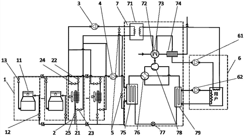
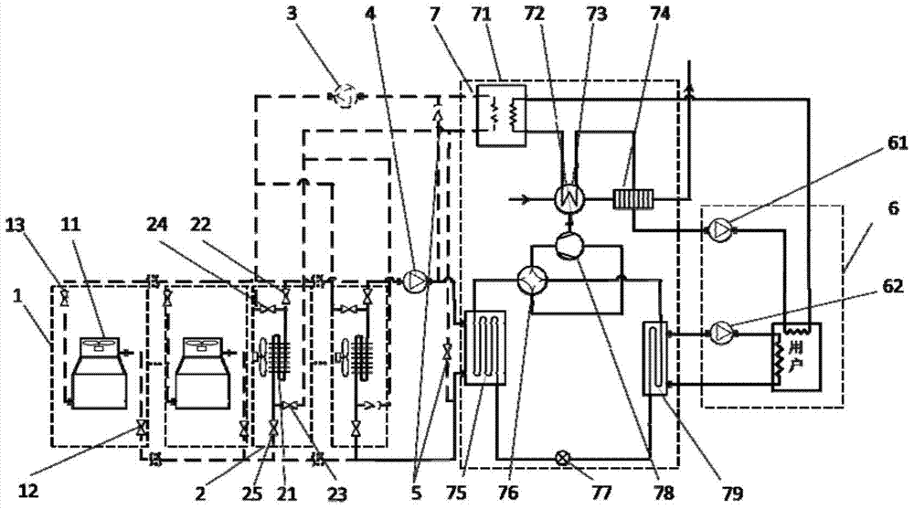
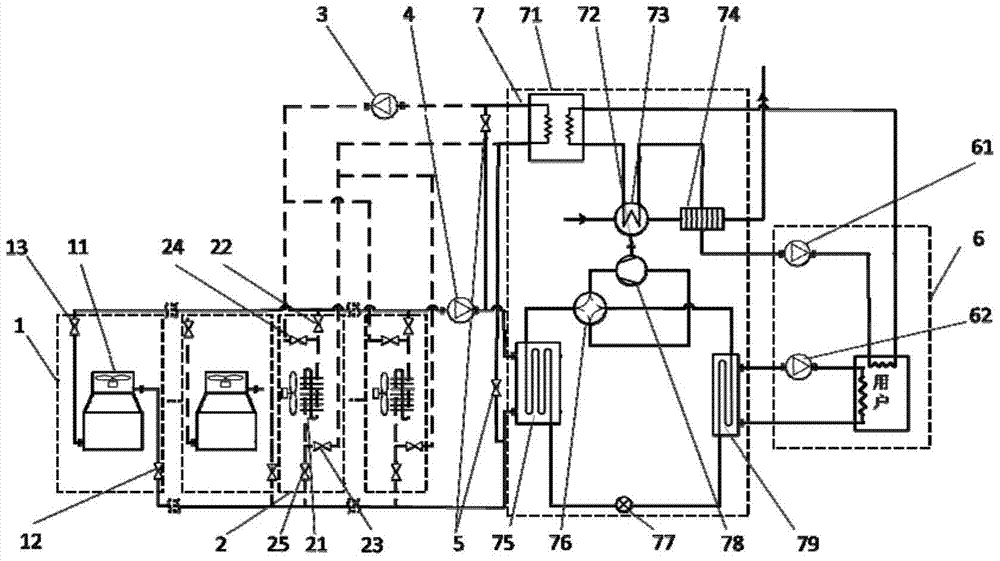
[0020] figure 1 It is an air source flexible gas heat pump unit disclosed in the present invention. The unit includes an outdoor unit, a gas heat pump unit and a user unit; the gas heat pump unit includes a waste heat heat exchanger 71, an engine 73 and a flue gas heat recovery heat exchanger The gas engine part composed of 74 and the heat pump part composed of a first heat exchanger 75, a compressor 78, a second heat exchanger 79, a four-way valve 76 and a throttle valve 77 are connected by a linkage shaft 72; its characteristics In that: the outdoor unit includes at least one set of cooling tower modules 1, at least two sets of air-cooled heat exchanger modules 2, a first liquid pump 3 and a second liquid pump 4, and each set of cooling tower modules contains a cooling tower 11 and a first valve 12 and the second valve 13; each ...


PUM


Abstract

An air source flexible gas heat pump unit and an operation method thereof belong to the field of heat pumps. The system includes an outdoor unit, a gas heat pump unit, and a user unit. The outdoor unit includes at least two sets of air-cooled heat exchangers, only one less set of cooling towers, valves, the second liquid pump and the first liquid pump; the gas heat pump unit includes two parts: a gas engine and a heat pump unit, and the gas engine includes waste heat heat exchange heat exchanger, engine, flue gas heat recovery heat exchanger, the heat pump part includes a first heat exchanger, a compressor, a second heat exchanger, a four-way valve and a throttle valve, and both the first heat exchanger and the second heat exchanger It is a liquid medium heat exchanger, and the two parts are connected through the linkage shaft between the engine and the compressor; the invention can solve the problems of low operating efficiency of traditional air-cooled gas heat pumps in summer and inability to obtain heat efficiently in winter, and has a great impact on reducing energy consumption and pollution emissions play a huge role.

Description

technical field [0001] The invention relates to an air source heat pump unit and an operation method thereof, in particular to a gas heat pump unit, which belongs to the technical field of heat pumps. Background technique [0002] The gas engine heat pump is a heat pump unit driven by a gas engine. It can take heat from a low-temperature environment to heat a high-temperature environment, and there is a large amount of waste heat after gas combustion that can be directly used. Therefore, the system has relatively good performance in heating. However, when the unit is running in summer, the outdoor air-cooled heat exchanger cannot achieve a good heat removal effect, so the operating efficiency of the unit will be greatly reduced; at the same time, the outdoor heat exchanger should be used when the unit is used in areas with low temperature and high relative humidity. There will be more serious frosting phenomenon. Once frosting will seriously affect the heat exchange effect a...

Claims


Application Information

Patent Timeline
Patent Type & Authority Patents(China)
IPC IPC(8): F25B29/00F25B41/04F25B41/20
Inventor 李先庭尚升王宝龙石文星
Owner TSINGHUA UNIV
Why Eureka
Try Eureka