Star sensor reference cube-prism installation error calibration apparatus

A star sensor and installation error technology, which is applied in the field of calibration device for star sensor reference cube mirror installation error, can solve the problems of difficulty in guaranteeing machining accuracy, loss of measurement accuracy, large diameter of light pipe objective lens, etc., and achieve high-precision installation error Calibration, low technical level requirements, and the effect of avoiding random errors

Active Publication Date: 2016-02-10
BEIJING AEROSPACE INST FOR METROLOGY & MEASUREMENT TECH +1
View PDF9 Cites 32 Cited by
  • Summary
  • Abstract
  • Description
  • Claims
  • Application Information

AI Technical Summary

Problems solved by technology

[0004] Due to the large diameter of the light tube objective lens in the large-aperture light tube measurement method, the processing accuracy is difficult to guarantee and the processing cost is high
In addition, due to off-axis light measurement, aberrations such as chromatic aberration and spherical aberration after the optical path passes through the optical system will cause a certain loss of measurement accuracy, which cannot meet the requirements of high-precision measurement
Secondly, this measurement method can only measure the installation error between the star sensor and the reference cube in the pitch and azimuth directions, but cannot measure the installation error in the roll direction.
[0005] The combined measurement method of light pipe and star simulator Although the larger-diameter light pipe measurement method improves the measurement accuracy, it still cannot measure the installation error in the roll direction

Method used


Image

  • Star sensor reference cube-prism installation error calibration apparatus
  • Star sensor reference cube-prism installation error calibration apparatus
  • Star sensor reference cube-prism installation error calibration apparatus

Examples


Embodiment Construction

[0018] The present invention will be described in detail below in conjunction with the accompanying drawings and specific embodiments.

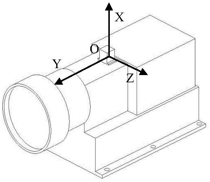
[0019] Such as figure 1 As shown, the reverse of the input optical axis of the star sensor 9 is defined as the Y axis, the outgoing normal direction of the plane on the reference cube mirror 10 is the X axis, and the Z axis is naturally generated by the right-handed spiral rule.

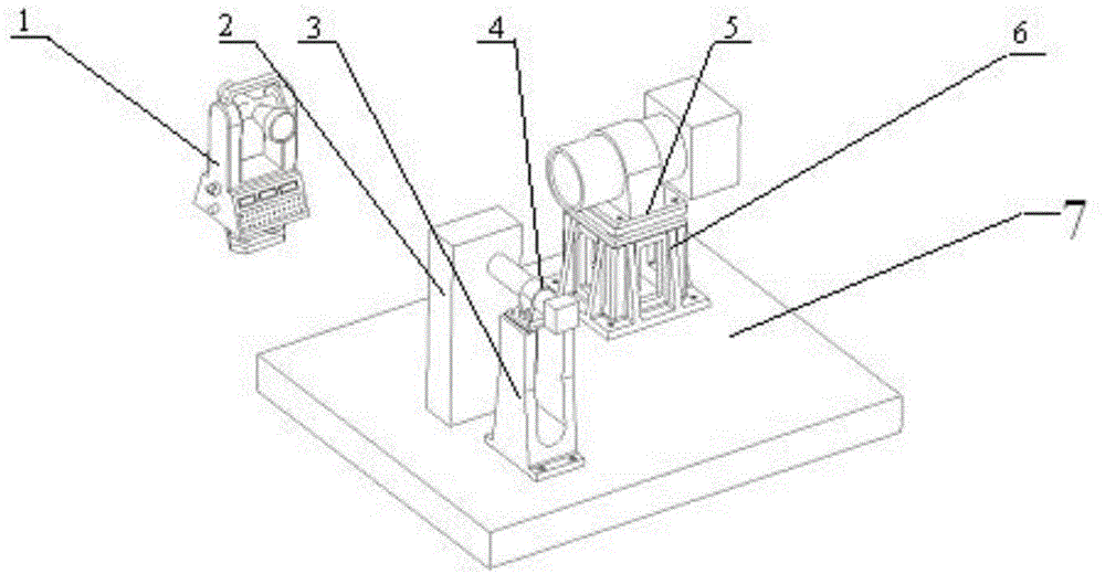
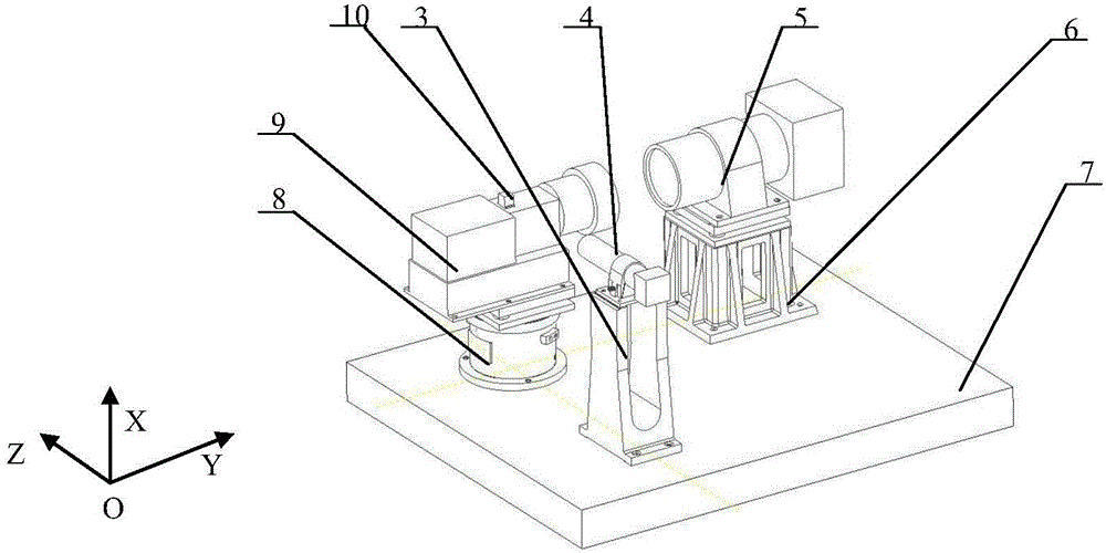
[0020] Such as figure 2 As shown, the photoelectric autocollimator 4 and the single star simulator 5 are respectively placed on two orthogonal axes on the reference plane 7, and the measured star sensor 9 is placed at the intersection of the two axes, and the photoelectric autocollimation The collimator 4 and the single-star simulator 5 are installed on the two-dimensional adjustment base 3 of the photoelectric autocollimator and the two-dimensional adjustment base 6 of the single-star simulator respectively, and the theodolite 1 connects the photoelectric autocol...


PUM


Abstract

The present invention belongs to the technical field of optoelectronic equipment calibration, and particularly relates to a star sensor reference cube-prism installation error calibration apparatus. According to the present invention, a photoelectric autocollimator and a single star simulator are respectively placed on two orthogonal axes of a reference plane, a detected star senor is placed at the intersection point position of the two axes so as to make the normal lines of the two orthogonal light reflection surfaces of the detected star senor reference prism be respectively parallel to the two orthogonal axes, the optical axes of the photoelectric autocollimator and the single star simulator are respectively adjusted to parallel to the reference plane through a theodolite, the star sensor is installed on a star sensor three-dimensional adjustment reference base, the input optical axis of the star sensor and the output optical axis of the single star simulator are adjusted to achieve a parallel state through the star sensor three-dimensional adjustment reference base, a detected reference cube-prism is arranged on the upper surface of the housing of the detected star senor, the installation angle error of the reference cube-prism round the X-axis and the Y-axis is measured by using photoelectric autocollimation, the star sensor three-dimensional adjustment reference base rotates 90 DEG, and the installation angle error of the reference cube-prism round the Z-axis is measured.

Description

technical field [0001] The invention belongs to the technical field of photoelectric equipment calibration, and in particular relates to a calibration device for installation errors of star sensor reference cube mirrors. Background technique [0002] As a high-precision space attitude optical sensor, the star sensor has been widely and deeply used in the aerospace field. Since the measurement coordinate system of the star sensor is virtual and invisible, it is necessary to accurately measure the position and attitude relationship between the measurement coordinate system of the star sensor and the coordinate system of the reference cube mirror on its shell during ground assembly, that is, the installation of the reference cube mirror error. That is, the geometric installation accuracy requirements of the star sensor on the spacecraft are realized by measuring the reference cube mirror on the star sensor. [0003] At present, there are mainly two methods for calibrating the...

Claims


Application Information

Patent Timeline
Patent Type & Authority Applications(China)
IPC IPC(8): G01C25/00
Inventor 姜云翔崔桂利郭雨蓉魏小林赵天承
Owner BEIJING AEROSPACE INST FOR METROLOGY & MEASUREMENT TECH
Why Eureka
Try Eureka