Unlock instant, AI-driven research and patent intelligence for your innovation.

Method and device for modifying uplink bearer

A technology for transmitting data and data, applied in the field of modification method and device for uplink bearing, capable of solving problems such as unproposed solutions, loss of uplink data, etc., and achieving the effect of reducing loss and reducing uplink data

Active Publication Date: 2019-12-24
ZTE CORP
View PDF7 Cites 0 Cited by
  • Summary
  • Abstract
  • Description
  • Claims
  • Application Information

AI Technical Summary

Problems solved by technology

For split bearer, currently only downlink split is supported. Uplink data is only sent through one base station. This sending base station is specified by upper-layer signaling. At the same time, in order to obtain shorter delay or SeNB path loss The uplink data transmission can be changed from this base station to another base station. When the terminal receives the uplink data transmission change command, the terminal and the old uplink transmission base station still have data to be sent, or there is still data in the buffer ready to be sent. In this case, since the uplink data cannot be sent to the two base stations at the same time, the uplink data may be lost
[0006] For the problem of how to reduce the loss of uplink data when a dual-connection terminal performs changes in uplink data transmission in the related art, no effective solution has been proposed so far

Method used


Image

  • Method and device for modifying uplink bearer
  • Method and device for modifying uplink bearer
  • Method and device for modifying uplink bearer

Examples


Embodiment 1

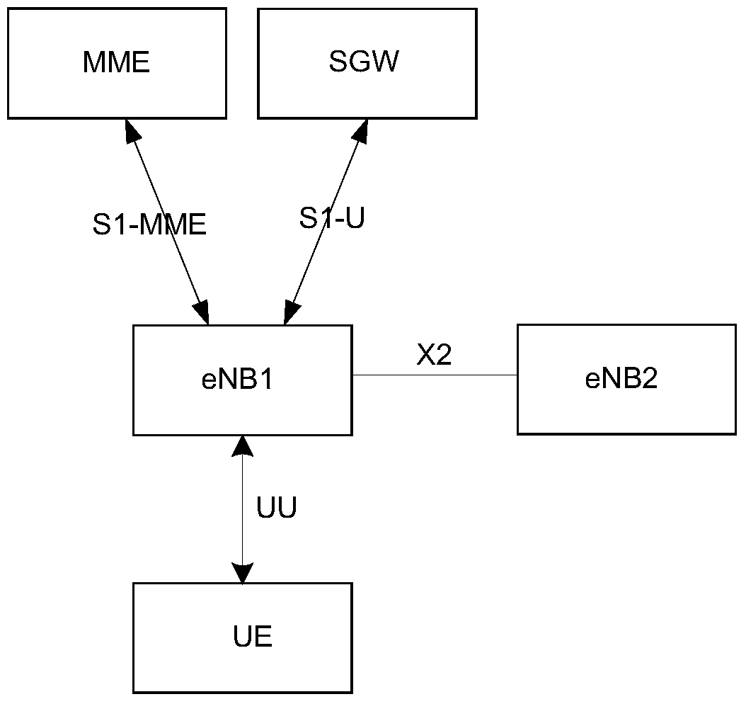
[0055] In this embodiment, the terminal establishes a connection with cell 1, configures cell 3 at the same time, and establishes a data radio bearer identifier of 1. Data radio bearer 1 exists on base station 1 and base station 2 at the same time, and is a split data radio bearer. , the base station 1 notifies the terminal that all the uplink data transmission of the divided data radio bearer is performed through the base station 1, and at this time there is only one divided radio data bearer, and the uplink data transmission is through the base station 1.

[0056] Figure 7 It is a flow chart of changing the uplink data sending node in this embodiment, such as Figure 7 As shown, it mainly includes the following steps:

[0057] Step 701, in the uplink data transmission of the split radio bearer, due to the increase of the uplink load of the base station 1, the base station 1 decides to move the uplink data transmission of the data radio bearer 1 to the base station 2, and s...

Embodiment 2

[0066] In this embodiment, the terminal establishes a connection with cell 1, configures cell 3 at the same time, and establishes data radio bearer identification as 1 and data radio bearer 2. Data radio bearers 1 and 2 exist on base station 1 and base station 2 at the same time. It is a split data radio bearer. At the same time, base station 1 notifies the terminal that the uplink data transmission of split data radio bearer 1 is all performed by base station 1, and the uplink data transmission of split data radio bearer 2 is all performed by base station 2.

[0067] The process of changing the uplink data sending node in this embodiment is similar to that in Embodiment 1, and mainly includes the following steps:

[0068] Step 1: Due to the increase of the uplink load of base station 1, base station 1 decides to move the uplink data transmission of data radio bearer 1 to base station 2, and sends a SeNB modification request to base station 2, which can carry the configuration ...

Embodiment 3

[0075] In this embodiment, the terminal establishes a connection with cell 1, configures cell 3 at the same time, and establishes a data radio bearer identifier of 1. Data radio bearer 1 exists on base station 1 and base station 2 at the same time, and is a split data radio bearer. , the base station 1 notifies the terminal that the uplink data is sent through the base station 2 .

[0076] Figure 8 It is a flow chart of changing the uplink data sending node in this embodiment, such as Figure 8 As shown, it mainly includes the following steps:

[0077] Step 801 , dividing the uplink data transmission of radio bearers, base station 1 decides to move the uplink data transmission of data radio bearer 1 to base station 1 due to the increased load of base station 2 . At this time, since the uplink data transmission of the data radio bearer 1 is deleted on the base station 2, there is no need to negotiate with the base station 2.

[0078] Step 802, base station 1 sends a data be...


PUM


Abstract

The invention discloses an uplink bearer modification method and device. Wherein, the method includes: the terminal in the dual connection receives an uplink data sending node change command, wherein the uplink data sending node change command instructs the terminal to change the uplink data sent through the first uplink data sending node to the second uplink data sending node. Send; the terminal continues to send some or all of the uplink data in the wireless link control RLC layer and media access control MAC layer buffers that already exist in the terminal and correspond to the first uplink data sending node through the first uplink data sending node; the terminal Clear the uplink data in the RLC layer and MAC layer buffers corresponding to the first uplink data sending node.

Description

technical field [0001] The present invention relates to the communication field, in particular, to a method and device for modifying an uplink bearer. Background technique [0002] figure 1 It is a schematic diagram of the overall architecture of the LTE system in the prior art, such as figure 1 As shown, the architecture of the LTE system mainly includes: Mobility Management Entity (MME, Mobility Management Entity), Serving Gateway (SGW, Serving GetWay), User Equipment (UE, User Equipment) and base station (eNB, eNodeB). Among them, the interface between UE and eNB is UU interface, the interface between eNB and MME is S1-MME (S1 for the control plane) interface, the interface between eNB and SGW is S1-U interface, and the interface between two eNBs The interface is the X2 interface. Here, UE may also be called a terminal. [0003] figure 2 It is a schematic diagram of a protocol architecture of a user plane between an LTE UE and an eNB in ​​the related art. The inter...

Claims


Application Information

Patent Timeline
Patent Type & Authority Patents(China)
IPC IPC(8): H04W72/04H04L1/18
CPCH04W88/06H04W36/0069H04W36/0064
Inventor 陈中明
Owner ZTE CORP