An anti-clogging and easy-to-clean microporous ceramic drip irrigation device

A microporous ceramic, easy-to-clean technology, applied in watering devices, horticulture, botanical equipment and methods, etc., can solve problems such as inability to clean, complex labyrinth channel structure, easy deposition, etc., to improve irrigation uniformity, work The principle is simple, and the effect of improving the anti-blocking performance

Inactive Publication Date: 2018-07-24
NORTHWEST A & F UNIV
View PDF7 Cites 0 Cited by
  • Summary
  • Abstract
  • Description
  • Claims
  • Application Information

AI Technical Summary

Problems solved by technology

However, the structure of the labyrinth flow channel inside these two emitters is relatively complex, and the manufacturing difficulty is relatively high. During injection molding, affected by factors such as raw materials and injection molding process, defects such as cold shut and lack of material are prone to occur near the labyrinth flow channel, which is serious. Affect the accuracy of the labyrinth flow channel; the difference in the assembly process of the inner core and the jacket of the emitter will also affect the overall accuracy of the emitter
These two factors are bound to seriously affect the irrigation uniformity of the emitter
In addition, the labyrinth channel emitter has high requirements on the water quality of the irrigation water. Solid impurities in poor water quality are easily deposited in the labyrinth flow channel of the emitter, causing blockage of the emitter, and after the emitter is blocked, it cannot be cleaned. Can be scrapped

Method used


Image

  • An anti-clogging and easy-to-clean microporous ceramic drip irrigation device
  • An anti-clogging and easy-to-clean microporous ceramic drip irrigation device
  • An anti-clogging and easy-to-clean microporous ceramic drip irrigation device

Examples


Embodiment Construction

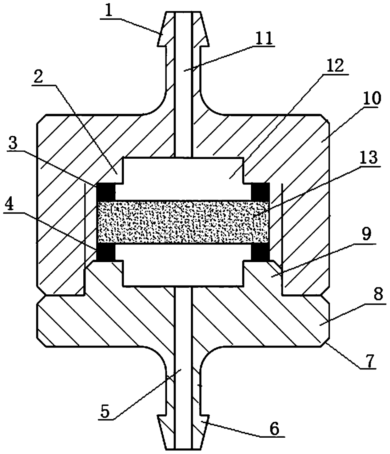
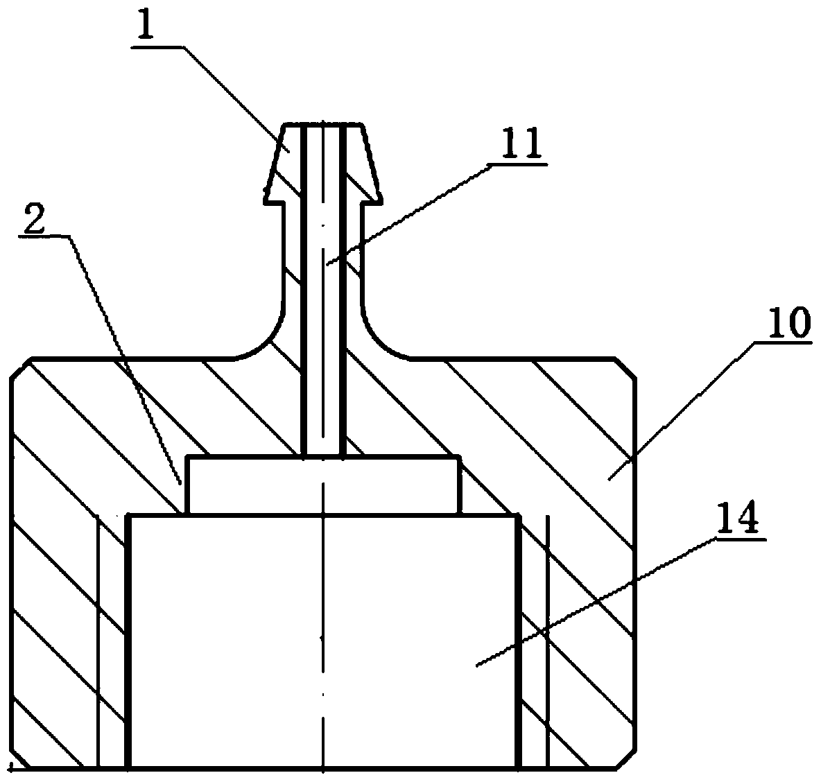
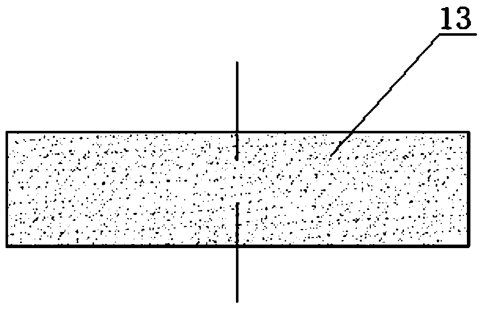
[0030] Comply with the above technical solutions, such as figure 1 As shown in Fig. 7, an anti-clogging and easy-to-clean microporous ceramic drip irrigation emitter includes a base 8 on which a cavity shell 10 is detachably installed, and a cavity 14 is provided inside the cavity shell 10, and the cavity 14 is installed with a water seepage sheet 13, and pores are distributed in the water seepage sheet 13; a water inlet hole 11 connected with the cavity 14 is provided on the cavity shell 10, and a water inlet hole 11 is provided on the base 8. The water outlet hole 5, the water flow enters the cavity 14 from the water inlet hole 11 and flows out of the base 8 from the water outlet hole 5 after being filtered by the water seepage sheet 13.

[0031] The basic structure of the present invention includes a base 8 and a cavity shell 10, wherein the inside of the cavity shell 10 is a cavity 14, and the cavity 14 has multiple functions, one of which is used to install the water seep...


PUM


Abstract

The invention discloses an anti-clogging easy-to-clean microporous ceramic drip irrigation emitter which comprises a pedestal, wherein a cavity housing is detachably mounted on the pedestal; the inner part of the cavity housing is provided with a cavity; a water seepage sheet is mounted in the cavity; pores are distributed in the water seepage sheet; a water inlet which is communicated with the cavity is formed in the cavity housing; a water outlet which is coaxial with the water inlet is formed in the pedestal; water flow flows into the cavity from the water inlet, and then flows out of the pedestal from the water outlet after being filtered by the water seepage sheet. During irrigation, pressure irrigation water with impurities enters the cavity from the water inlet, then, the impurities are filtered on the upper surface of the microporous ceramic water seepage sheet, the irrigation water slowly seeps downwards by virtue of pore paths which are communicated with each other inside the microporous ceramic water seepage sheet, and finally flows out uniformly and stably from the water outlet below the irrigation emitter. The irrigation emitter has the advantages of being simple in an energy-consuming structure, high in uniformity, resistant to clogging, easy to clean, and the like; the microporous ceramic water seepage sheet inside the irrigation emitter can be repeatedly cleaned for use, so that manufacturing cost of the irrigation emitter is remarkably reduced.

Description

technical field [0001] The invention belongs to the technical field of agricultural water-saving irrigation in arid areas, and relates to an anti-clogging and easy-to-clean microporous ceramic drip irrigation water device, which is used to solve the problem of water-saving irrigation of large fields and economic crops. Background technique [0002] Water-saving irrigation is the main irrigation method used in modern agriculture, especially in dry areas. As an advanced water-saving irrigation technology, micro-irrigation has been widely used in crop irrigation in dry areas. Through reasonable system design and efficient field management, micro-irrigation can realize regular and appropriate irrigation of crop roots, effectively reduce the evaporation of ground water, and greatly improve the utilization efficiency of irrigation water. The emitter is the most critical component of the micro-irrigation system. The structure, hydraulic performance and quality of the emitter direct...

Claims


Application Information

Patent Timeline
Patent Type & Authority Patents(China)
IPC IPC(8): A01G25/02
CPCA01G25/02A01G25/026A01G2025/006
Inventor 李向明吴普特朱德兰蔡耀辉
Owner NORTHWEST A & F UNIV
Why Eureka
Try Eureka