Automatic planting system

A planting system and automatic technology, applied in botany equipment and methods, soilless cultivation, cultivation, etc., can solve problems such as pump burnout, cumbersome operation process, and different watering requirements

Inactive Publication Date: 2016-02-17
段卫东
View PDF3 Cites 2 Cited by
  • Summary
  • Abstract
  • Description
  • Claims
  • Application Information

AI Technical Summary

Problems solved by technology

However, in different stages of plant growth and under different weather conditions, the watering requirements are different, so it is necessary to set the timer multiple times, while setting the working time and liquid supply interval of ordinary timers requires careful reading of the timer manual, the operation process cumbersome
There is usually a container for storing nutrient solution in the planting device, and it can be automatically watered within a certain period of time after a nutrient solution is replenished. The pump idling caused by too low is very easy to cause the pump to burn out

Method used


Image

  • Automatic planting system

Examples


Embodiment Construction

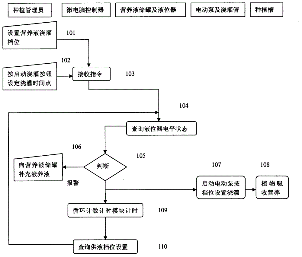
[0010] In a specific implementation, the submersible pump or pump water inlet is placed in the nutrient solution storage tank, its water outlet is connected to the irrigation pipe leading to the plants in the planting tank, and its power supply is connected to the power output of the microcomputer controller. The liquid level gauge stands in the liquid of the liquid storage tank and dips to the bottom. Its output signal line is connected to the microcomputer controller. The float valve is placed at the bottom of the liquid level gauge. When the liquid level is higher than the position of the pump inlet, the float valve floats. When the position is lower than the water inlet position of the pump, the float valve falls to start the internal reed to switch on and change the level, and an alarm message is given. The control panel of the microcomputer controller is equipped with a multi-position toggle or selection interlock switch, which is used to select the length of watering tim...


PUM


Abstract

Provided is an automatic planting system, formed by a micro-computer controller, an electric pump, and irrigating pipes, a nutrient solution storage tank, a liquid level device, and plant slots.

Description

technical field [0001] The invention relates to a plant automatic planting system. Background technique [0002] One of the development directions of modern agriculture is high-efficiency planting and production on the balconies of urban buildings. While beautifying the environment and reducing local environmental pollution, it can also achieve self-sufficiency in the supply of some green agricultural products. Europe, the United States and Japan have begun to popularize the planting technology of agricultural products on the roofs of urban balconies. [0003] A large number of related patents can be found by searching for patents with soilless cultivation devices and balcony planting devices, which can be roughly divided into three categories in terms of content: one category includes planting irrigation devices with different structures, such as CN203505235U[Chinese]CN203505235U[English] Invention name - an invention of a balcony planting device and components; the second ...

Claims


Application Information

Patent Timeline
Patent Type & Authority Applications(China)
IPC IPC(8): A01G31/02
CPCY02P60/21
Inventor 段卫东
Owner 段卫东
Why Eureka
Try Eureka