Spiral magnetic separator

A magnetic separator and spiral technology, applied in the field of mining machinery, can solve the problems of low recovery rate and achieve high recovery rate, simple and compact structure, and strong corrosion resistance

Inactive Publication Date: 2016-02-17
谢福星
View PDF8 Cites 6 Cited by
  • Summary
  • Abstract
  • Description
  • Claims
  • Application Information

AI Technical Summary

Problems solved by technology

[0003] The object of the invention of the present invention is to: aim at the above-mentioned existing problems, provide a kind of spiral magnetic separator with simple and compact structure, small footprint, mainly solve the low recovery rate of some weak magnetic ore particles in the existing magnetic separator, The problem of low concentrate grade, improve the beneficiation efficiency, solve the problem of magnetization of the non-magnetic part of the magnetic separator, improve the adaptability of the magnetic separator, and enhance the corrosion resistance of the magnetic separator

Method used


Image

  • Spiral magnetic separator
  • Spiral magnetic separator

Examples


Embodiment Construction

[0026] Below in conjunction with accompanying drawing, the present invention is described in detail.

[0027] In order to make the object, technical solution and advantages of the invention clearer, the present invention will be further described in detail below in conjunction with the accompanying drawings and embodiments. It should be understood that the specific embodiments described here are only used to explain the present invention, not to limit the present invention.

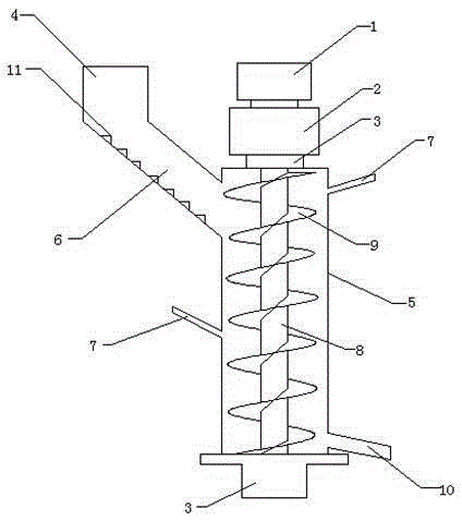
[0028] Such as figure 1 As shown, a spiral magnetic separator includes a machine base 3, a feed port 4, a beneficiation chamber 5 and a tailings outlet pipe 10, the top of the beneficiation chamber 5 is connected to a machine base, and one side of the upper part of the beneficiation chamber 5 A feed port 4 is provided, a flushing device 7 is provided on the other side of the upper part, a flushing device 7 is provided on one side of the middle and lower part of the mineral processing chamber 5, and a tai...


PUM


Abstract

The invention discloses a spiral magnetic separator. The spiral magnetic separator comprises a machine base, a feed inlet, a mineral separation cavity and a tailing outlet pipe. The top end of the mineral separation cavity is connected with the machine base. The feed inlet is formed in one side of the upper portion of the mineral separation cavity. A flushing device is arranged on the other side of the upper portion of the mineral separation cavity. A flushing device is arranged on one side of the middle lower portion of the mineral separation cavity. The tailing outlet pipe is arranged on one side of the lower portion of the mineral separation cavity. The lower end of the mineral separation cavity is connected to the machine base. A rotary shaft is arranged inside the mineral separation cavity. The upper end of the rotary shaft is fixedly connected to a bearing seat of the machine base. A U-shaped groove is wound on the rotary shaft. The spiral magnetic separator is simple and compact in structure and small in occupied area; the problems that when an existing magnetic separator is used for separating certain weakly-magnetic mineral grains, the recovery rate is low, and the concentrate grade is low are mainly solved; the mineral separation efficiency is improved; the problem that a non-magnetic part of the magnetic separator is magnetized is also solved; the adaptive capacity of the magnetic separator is improved, and the corrosion resistance of the magnetic separator is also improved.

Description

technical field [0001] The invention relates to the field of mining machinery, in particular to a spiral magnetic separator for mining. Background technique [0002] At present, the magnetic separators used to process magnetite-type iron ore are generally drum-type magnetic separators. Because the drum of the drum-type magnetic separator needs to rotate continuously, and the magnetic system in the drum must remain fixed, so There is a gap between the magnetic system and the inner wall of the drum, which weakens the magnetic field strength of the outer wall of the drum, so that the magnetic energy of the magnetic system cannot be fully utilized. Magnetic separators, especially strong magnetic separators, are seldom used in ilmenite beneficiation operations. Generally, only weak magnetic ones are used for iron removal of ilmenite ore materials, while sand-titanium ore is beneficiated with spiral rollers, which has poor adaptability and low recovery rate. And the concentrate g...

Claims


Application Information

Patent Timeline
Patent Type & Authority Applications(China)
IPC IPC(8): B03C1/02
CPCB03C1/02B03C1/284B03C1/286B03C2201/18
Inventor 肖勇
Owner 谢福星
Why Eureka
Try Eureka