A three-dimensional laser engraving machine

A laser engraving and three-dimensional technology, applied in welding equipment, laser welding equipment, metal processing equipment, etc., can solve the problem of engraving high-quality large workpieces, long workpieces that cannot achieve multiple positioning engraving, and machines that do not have rotation , stretching and other issues, to achieve the effect of high rigidity, simple structure and high technical added value

Active Publication Date: 2017-07-28
常德市德源招商投资有限公司
View PDF7 Cites 0 Cited by
  • Summary
  • Abstract
  • Description
  • Claims
  • Application Information

AI Technical Summary

Problems solved by technology

This structure can generally only be used to process workpieces with a small format, and because it needs to drive a heavy worktable, its positioning speed and dynamic response are poor
Therefore, the current three-dimensional laser engraving machine cannot realize multiple positioning engraving for long workpieces beyond the stroke range of the machine tool, and cannot meet the requirements of engraving high-quality and large-scale workpieces.
At the same time, the existing three-dimensional laser engraving machine can only realize three-axis linkage of X-axis, Y-axis and Z-axis. The whole machine does not have functions such as rotation and expansion, which makes the movement of the machine inflexible and inconvenient to cut workpieces, resulting in low work efficiency. Engraving quality cannot be guaranteed

Method used


Image

  • A three-dimensional laser engraving machine
  • A three-dimensional laser engraving machine
  • A three-dimensional laser engraving machine

Examples


Embodiment 1

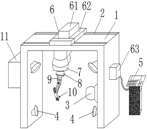
[0021] The present invention provides such Figure 1-3 A three-dimensional laser engraving machine shown includes a bracket 1, an FPGA control device 5, a transmission mechanism 6 and a mechanical transmission device 9, two groups of reflective convex mirrors 4 are symmetrically arranged on the two inner surfaces of the bracket 1, and the bracket The top of 1 is provided with guide rail 2, and described guide rail 2 is arranged as groove-shaped guide rail, and described guide rail 2 is symmetrically arranged in two groups, and the inner surface of described support 1 is provided with CCD camera device 3, and described CCD camera device 3 passes through Wire is electrically connected with FPGA control device 5, and described transmission mechanism 6 comprises servomotor 61 and slide block 62, and described servomotor 61 is connected with slide block 62 transmission, and the right side of described support 1 is fixed with driver 63, and described Driver 63 is electrically connec...

Embodiment 2

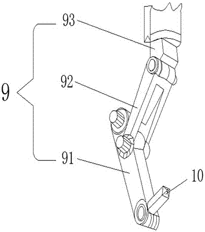
[0023] In addition to being the same as Embodiment 1, this embodiment is Figure 4Another structural schematic diagram of the mechanical transmission device, the mechanical transmission device 9 includes an X-axis drive device 94 and a Y-axis hydraulic telescopic device 95, and the X-axis drive device 94 includes an X-axis transmission block 941, an X-axis servo motor 942 and a fixed seat 943, the fixed seat 943 is fixedly connected with the laser 8 through a bearing, the front of the fixed seat 943 is provided with an X-axis guide rail 944, and the X-axis transmission block 941 is connected to the X-axis guide rail 944 in transmission, so The X-axis servo motor 942 is installed on the side of the X-axis transmission block 941 , the Y-axis hydraulic telescopic device 95 is provided with a hydraulic telescopic rod 951 , and the laser engraving head 10 is installed at the bottom of the hydraulic telescopic rod 951 . In this embodiment, the X-axis transmission block 941 is driven...


PUM


Abstract

The invention discloses a three-dimensional laser engraving machine, which includes a bracket, an FPGA control device, a transmission mechanism and a mechanical transmission device. The top of the bracket is provided with a guide rail, and the servo motor is connected to the slider. The right side of the bracket is A driver is fixed, the driver is electrically connected to the servo motor and the FPGA control device through wires, the slider is slidably connected to the guide rail, the servo DC rotary motor is electrically connected to the FPGA control device, and the servo DC rotary motor The output shaft of the laser is connected to a laser through a coupling, and the lower end of the laser is fixedly connected to the mechanical transmission device. The lower end of the mechanical transmission device is provided with a laser engraving head. The present invention has simple structure, simple operation, complex and accurate mathematical operations, It has outstanding advantages such as high rigidity, fast response, high precision, strong adaptability, high technical added value and strong flexibility.

Description

technical field [0001] The invention belongs to the technical field of laser engraving, and in particular relates to a three-dimensional laser engraving machine. Background technique [0002] Laser engraving technology belongs to a relatively common laser processing technology. Laser engraving processing mainly uses the vaporization effect, photochemical effect and flame erosion effect of laser on the workpiece to achieve the processing effect. Laser engraving has the characteristics of non-contact, low noise, high speed, etc. It is very suitable for engraving and processing of non-metallic materials such as acrylic, rubber, wood, etc., and has been widely used in industries such as advertising, clothing, printing, and handicrafts. [0003] Most of the traditional three-dimensional laser engraving machines adopt a mobile table and fixed beam gantry structure. Generally, this structure can only be used to process workpieces with a small format, and because it needs to drive ...

Claims


Application Information

Patent Timeline
Patent Type & Authority Patents(China)
IPC IPC(8): B23K26/362B23K26/70
Inventor 田璐陈华冯杰
Owner 常德市德源招商投资有限公司
Why Eureka
Try Eureka