
Clamping and forced conveying mechanism based on discharging end of vertical-axis ripping saw

A technology of conveying mechanism and splitting saw, which is used in circular saws, unloading equipment, manufacturing tools, etc., can solve the problems of reducing product quality, material jamming, material breaking, etc., and achieves improved production efficiency, high surface quality, and application scope. wide effect

Active Publication Date: 2016-02-17
SICHUAN QINGCHENG MACHINERY
View PDF9 Cites 1 Cited by
  • Summary
  • Abstract
  • Description
  • Claims
  • Application Information

AI Technical Summary

Problems solved by technology

[0003] The vertical axis splitting saw is one of the main equipments for wood processing. After the existing vertical axis splitting saw splits the wood, the wood is transported forward through the feeding side feeding mechanism. When splitting the rear end of the wood, The feeding mechanism on the feeding side can no longer provide forward power, and it is prone to material jams and material breaks, which will reduce product quality. The usual method is that when most of the wood is split, the staff pulls the split on the discharge side. The divided wood greatly increases the labor load of the staff

Method used


Image

  • Clamping and forced conveying mechanism based on discharging end of vertical-axis ripping saw
  • Clamping and forced conveying mechanism based on discharging end of vertical-axis ripping saw
  • Clamping and forced conveying mechanism based on discharging end of vertical-axis ripping saw

Examples


Embodiment Construction

[0021] The present invention will be further described below in conjunction with the accompanying drawings, but the protection scope of the present invention is not limited to the following description.

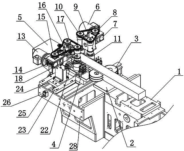
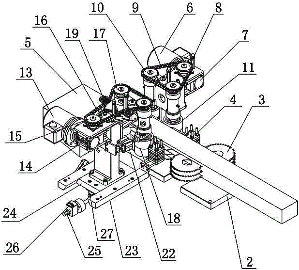
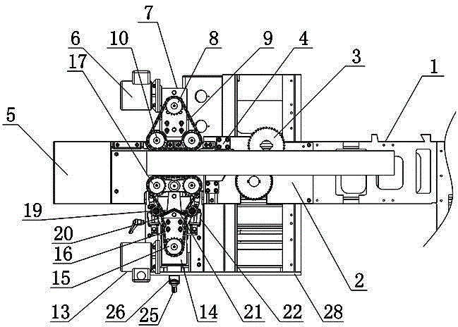
[0022] Such as figure 1 As shown, the clamping and forced conveying mechanism at the discharge end of the saw based on the split vertical axis includes a machine base 1, a workbench 2 fixed above the machine base 1, a saw blade 3, a fixed-side conveying assembly, a swinging-side conveying assembly, and a swinging assembly. The machine base 1 is made of high-quality castings. After special heat treatment and precision machining, the stability of the machine base 1 is enhanced and its precision is improved. The saw blade 3 is installed above the workbench 2 through the rotation of the saw shaft. The saw shaft is driven by the saw motor to rotate. The blade 3 is directly installed on the saw shaft, which can reduce the diameter of the saw blade 3, so that thin saw blade processi...


PUM


Abstract

The invention relates to a clamping and forced conveying mechanism based on a discharging end of a vertical-axis ripping saw. The mechanism comprises a base, a worktable, saw blades, a fixed side conveying assembly, a swinging side conveying assembly and a swinging assembly, wherein the worktable, the saw blade, the fixed side conveying assembly, the swinging side conveying assembly and the swinging assembly are arranged above the base; the fixed side conveying assembly and the swinging side conveying assembly are oppositely arranged at a discharging side of the worktable; the fixed side conveying assembly comprises a fixed side motor, a fixed side speed reducer, fixed side driving chain wheels, fixed side driven chain wheels and fixed side feeding rollers; the swinging side conveying assembly comprises a swinging side motor, a swinging side speed reducer, a swinging side driving chain wheels, swinging side driven chain wheels and swinging side feeding rollers; the swinging assembly comprises embedding strips, a feeding sliding plate and a feeding and returning lead screw. The mechanism has the advantages that the forced conveying mechanism is adopted at the discharging side and can effectively prevent materials from blocking and breaking; in addition, the production efficiency is high, the product quality is high, the workload of operators can be decreased, and meanwhile, the mechanism is applicable to forced conveying of wood materials with different widths.

Description

technical field [0001] The invention relates to a feeding device for a split saw, in particular to a clamping and forced conveying mechanism based on a vertical shaft split saw discharge end. Background technique [0002] In recent years, wood processing has become a stable process system with increasing specialization. The application of electronic computers has played an important role in the innovation of wood-making technology, the transformation of the wood product processing industry system, and the development of wood-based panel production technology and product design engineering. Under the influence of the new technological revolution, all indicate that wood processing technology will undergo further major changes. [0003] The vertical axis splitting saw is one of the main equipments for wood processing. After the existing vertical axis splitting saw splits the wood, the wood is transported forward through the feeding side feeding mechanism. When splitting the re...

Claims


Application Information

Patent Timeline
Patent Type & Authority Applications(China)
IPC IPC(8): B27B5/06B27B5/29B27B31/08
CPCB27B5/06B27B5/29B27B31/08
Inventor 鲁素勤王云清
Owner SICHUAN QINGCHENG MACHINERY
Learn More