Method for calibrating flatness of X-Y plane of microscopic scanning platform

A scanning platform and calibration method technology, applied in microscopes, optics, instruments, etc., can solve problems such as increased hardware complexity, out-of-focus, and increased cost expenditures, and achieve the goal of reducing improvement costs, reducing manufacturing costs, and improving continuous scanning performance Effect

Inactive Publication Date: 2016-02-17
SUZHOU CHUANGJI BIOLOGICAL TECH
View PDF3 Cites 12 Cited by
  • Summary
  • Abstract
  • Description
  • Claims
  • Application Information

AI Technical Summary

Problems solved by technology

[0010] The third premise: the moving stroke of the XY scanning platform is at least 25mm in the Y direction and 75mm in the X direction, generally X100mm and Y75mm. Factors, the height difference (flatness) of the entire movement is about 2um, which has exceeded the focal plane depth of field of the lens, and some areas will appear out of focus during continuous scanning
[0011] If you use a platform with higher precision guide rails, the cost will rise linearly, and the hardware complexity will also increase (such as using magnetic levitation guide rails)

Method used


Image

  • Method for calibrating flatness of X-Y plane of microscopic scanning platform
  • Method for calibrating flatness of X-Y plane of microscopic scanning platform
  • Method for calibrating flatness of X-Y plane of microscopic scanning platform

Examples


Embodiment

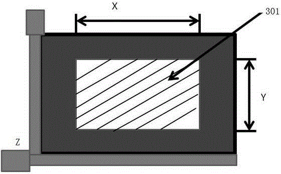
[0096] The following embodiments describe the calibration method of the microscopic scanning platform in detail. In this embodiment, the moving area of ​​the scanning platform is 100mm * 75mm=7500mm 2 The detailed process steps of its calibration are as follows:

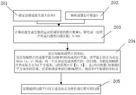
[0097] first step, such as figure 2 As shown in steps 201 and 202, determine the magnification of the microscope lens, the target surface S of the camera imaging chip, and the lens magnification X of the microscope, so as to calculate the physical area S on the XY platform corresponding to the camera imaging photo.

[0098] The second step, such as figure 2 As shown in step 203, calculate the moving area S of the scanning platform, that is, S=100mm×75mm=7500mm 2 , set the camera image size to cover the entire motion area, and calculate the number N of photos required to capture the complete motion area, then N=7500.

[0099] The third step is to determine the XY axis coordinates of each photo taken. If the actua...


PUM


Abstract

The invention discloses a method for calibrating flatness of an X-Y plane of a microscopic scanning platform. The method comprises the following steps: (1) defining a coordinate system of a plane of the microscopic scanning platform through a control unit; (2) selecting a standard stripe slide, calculating a scanning height corrected value of each scanning point, and storing the corrected value corresponding to each calculated coordinate point into a storage unit in the control unit; (3) calculating the coordinate of a scanning corrected value of each coordinate point n in the coordinate system of the scanning platform, and recording a corrected coordinate value corresponding to the standard stripe slide into storage unit in the control unit; (4) reversely loading a scanning corrected coordinate of the standard stripe slide corresponding to the coordinate point recorded in the storage unit of the control unit, or calculating a theoretical plane scanning height according to the corrected value, and transmitting a corrected actual scanning focusing height value to the control unit; and (5) issuing an instruction by the control unit to drive a driver to carry out scanning imaging.

Description

technical field [0001] The invention relates to the technical field of microscopic scanning precision, in particular to a flatness calibration method of an XY plane of a microscopic scanning platform. Background technique [0002] Microscope is a common tool for observing the microscopic world, and is currently widely used in biomedical diagnostic research and industrial production. At present, the use of automatic microscopy is more and more widely, that is, the movement of the slide on the stage, the focus between the lens and the sample, and the shooting of the sample image are all controlled by the automated XY axis platform, Z axis lens drive and digital camera. The linkage is complete. [0003] Usually microscopic observation samples are placed on a glass slide (25mmx75mm) for transmitted light illumination (mostly biological samples) or placed directly on the stage for illumination by epi-light (mostly for industrial use), if the tolerance of the sample plane is with...

Claims


Application Information

Patent Timeline
Patent Type & Authority Applications(China)
IPC IPC(8): G02B21/36
CPCG02B21/365
Inventor 殷跃锋
Owner SUZHOU CHUANGJI BIOLOGICAL TECH
Why Eureka
Try Eureka