
Low-voltage switch box convenient to install

A power distribution cabinet and low-voltage technology, applied in the field of power distribution cabinets, can solve the problems of troublesome installation, maintenance and replacement of electrical components, low work efficiency, cumbersome installation process, etc., and achieve the effects of convenient installation and operation, time saving and simple structure

Inactive Publication Date: 2016-02-17
STATE GRID CORP OF CHINA +1
View PDF4 Cites 18 Cited by
  • Summary
  • Abstract
  • Description
  • Claims
  • Application Information

AI Technical Summary

Problems solved by technology

[0002] The low-voltage power distribution cabinet is used for power conversion and control of lighting and power distribution. It is widely used because of its strong breaking capacity, good dynamic and thermal stability, flexible electrical scheme, convenient combination, series, strong practicability, and novel structure. Application, in the environment where the market demand for low-voltage power distribution cabinets in my country is strong, the competition within the industry will intensify. Suppliers who provide a new generation of low-voltage complete sets of equipment and system solutions will gain opportunities in the future market competition. Traditional distribution cabinets From the structure of the electric cabinet itself, including the cabinet body and the electrical components installed in the cabinet, the circuit breaker is the most commonly used one, especially in the low-voltage power distribution cabinet, but the installation process is very cumbersome, and the installation is troublesome. It takes a long time, and the fixed mounting plate in the power distribution cabinet also brings some troubles to the installation, maintenance and replacement of electrical components, and the inconvenient operation leads to lower work efficiency. Therefore, we propose an easy-to-install low-voltage power distribution cabinet

Method used


Image

  • Low-voltage switch box convenient to install
  • Low-voltage switch box convenient to install
  • Low-voltage switch box convenient to install

Examples


Embodiment Construction

[0016] The following will clearly and completely describe the technical solutions in the embodiments of the present invention with reference to the accompanying drawings in the embodiments of the present invention. Obviously, the described embodiments are only some, not all, embodiments of the present invention. Based on the embodiments of the present invention, all other embodiments obtained by persons of ordinary skill in the art without making creative efforts belong to the protection scope of the present invention.

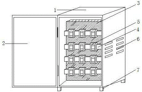
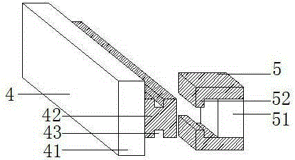
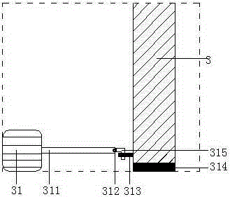
[0017] see Figure 1-3 , the present invention provides a technical solution: a low-voltage power distribution cabinet that is easy to install, including a cabinet body 1, the outer wall of the cabinet body 1 is hinged with a cabinet door 2, and the left and right side walls of the cabinet body 1 are provided with ventilation holes 6, To play the role of cooling the electrical components in the cabinet, the four corners of the bottom of the cabinet 1 are provi...


PUM


Abstract

The invention discloses a low-voltage switch box convenient to install. The low-voltage switch box convenient to install comprises a box body, wherein the outer wall of the box body is hinged with a box door via a hinge; the left and right side walls of the box body are provided with ventilation holes; four bottom angles of the box body are provided with support floor mats; the inner cavity of the box body is provided with a mobile installation plate which is movably provided with an installation row; the outer wall of the installation row is movably connected with a circuit breaker in an inserted mode; the installation row comprises insertion blocks, and the mobile installation plate is provided with slide ways matched with the insertion blocks; buckling blocks are fixed on the side wall of the insertion blocks; upper and lower ends of the buckling blocks are provided with grooves; the circuit breaker comprises a short-circuit panel; buckling elements are fixed on the upper and lower ends of the circuit breaker panel. The low-voltage switch box convenient to install is simple in structure, is convenient to operate, and enhances the installation efficiency effectively.

Description

technical field [0001] The invention relates to the technical field of power distribution cabinets, in particular to a low-voltage power distribution cabinet that is easy to install. Background technique [0002] The low-voltage power distribution cabinet is used for power conversion and control of lighting and power distribution. It is widely used because of its strong breaking capacity, good dynamic and thermal stability, flexible electrical scheme, convenient combination, series, strong practicability, and novel structure. Application, in the environment where the market demand for low-voltage power distribution cabinets in my country is strong, the competition within the industry will intensify. Suppliers who provide a new generation of low-voltage complete sets of equipment and system solutions will gain opportunities in the future market competition. Traditional distribution cabinets From the structure of the electric cabinet itself, including the cabinet body and the el...

Claims


Application Information

Patent Timeline
IPC IPC(8): H02B1/30H02B1/56
CPCH02B1/306H02B1/565
Inventor 王玉武王树明邵长凯王光辉类延峰
Owner STATE GRID CORP OF CHINA
Learn More