Optical instrument for automatically searching myofascitis trigger point

A myofascial and trigger point technology, which is applied in the field of automatic myofascial trigger point optical instrumentation, can solve the problem that subjects cannot measure by themselves, it is difficult to find pain points, and ordinary patients cannot accurately locate the trigger point of myofasciitis And other issues

Inactive Publication Date: 2016-02-24
INFINITUS (CHINA) CO LTD
View PDF5 Cites 0 Cited by
  • Summary
  • Abstract
  • Description
  • Claims
  • Application Information

AI Technical Summary

Problems solved by technology

[0004] At present, the following methods are mainly used to find the trigger point. The first method is to find the trigger point of myofasciitis through an acupuncturist or therapist, which is closely related to their experience; the other is to use a hand-held tenderness meter to measure the trigger point. The disadvantage of this method is that the subject cannot measure it by himself, and the subject easily misunderstands the pain tolerance threshold and the pain threshold, so it is difficult to find the exact pain point; there are also some such as fine needle electrode electromyography, Surface electromyography, ultrasound images and MRI have also been reported and applied to the detection of trigger points in recent years, but because most of them go to hospitals for testing and are mostly used for clinical trials, their promotion is widely limited by time and space, so there are certain limitations sex
[0005] In summary, the existing methods for finding the trigger point of myofasciitis have great limitations, and ordinary patients cannot accurately locate the trigger point of myofasciitis

Method used


Image

  • Optical instrument for automatically searching myofascitis trigger point
  • Optical instrument for automatically searching myofascitis trigger point
  • Optical instrument for automatically searching myofascitis trigger point

Examples


Embodiment Construction

[0025] The technical solutions in the embodiments of the present invention will be clearly and completely described below. Obviously, the described embodiments are only some of the embodiments of the present invention, but not all of them. Based on the embodiments of the present invention, all other embodiments obtained by persons of ordinary skill in the art without making creative efforts belong to the protection scope of the present invention.

[0026] In order to describe the present invention in more detail, an optical instrument for automatically finding myofascial trigger points provided by the present invention will be specifically described below in conjunction with embodiments.

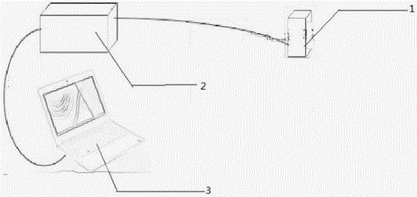
[0027] see figure 1 , the present invention provides an optical instrument for automatically finding myofascial trigger points, comprising: a fiber optic spectrometer 2, an integrating sphere 1 and a control device 3; the fiber optic spectrometer 2 and the integrating sphere 1 are electrical...


PUM

PropertyMeasurementUnit
Diameteraaaaaaaaaa
Wavelength rangeaaaaaaaaaa

Abstract

The invention belongs to the field of health-care equipment and particularly relates to an optical instrument for automatically searching a myofascitis trigger point, which is used for solving the problems that the existing method for searching the myofascitis trigger point has very great limitation and a common patient can not accurately position the myofascitis trigger point. The optical instrument for automatically searching the myofascitis trigger point, provided by the invention, comprises an optical fiber spectrometer, an integrating sphere and control equipment, wherein the optical fiber spectrometer is electrically connected with the integrating sphere; the control equipment is electrically connected with optical fiber spectrometer; and the integrating sphere is provided with a light source and a spectrophotometer. By virtue of the optical instrument for automatically searching the myofascitis trigger point, provided by the invention, the patient can accurately position the myofascitis trigger point; and the optical instrument also has the advantages of being noninvasive, small in volume and convenient to carry.

Description

technical field [0001] The invention belongs to the field of health care equipment, in particular to an optical instrument for automatically finding myofascial trigger points. Background technique [0002] Myofascitis, also known as myofascial pain syndrome (Myofascial Pain Syndrome, referred to as MPS), is a clinical common disease, frequently-occurring disease. It refers to one of the common clinical soft tissue injury diseases characterized by localized chronic muscle pain accompanied by one or more trigger points (TriggerPoints, TrPs for short). Diagnostic criteria are tender points, fixed pain, and bands of muscle tension, while referred pain and twitch responses are confirmatory signs of myofascial trigger points. Especially myofasciitis of the shoulder and back is clinically common. Myofasciitis of the shoulder and back is mostly seen in adults and the elderly, but with the development of society, the long use of computers and the acceleration of people's life rhyth...

Claims


Application Information

Patent Timeline
IPC IPC(8): A61B5/00A61H39/02
CPCA61B5/0075A61B5/4887A61H39/02
Inventor 钟会清姜雪梅杨辉周艳郭周义吴秀丽苏成康叶丙刚龙佳林锦
Owner INFINITUS (CHINA) CO LTD
Why Eureka
Try Eureka