Rotary working table

A technology of rotary workbench and worktable, applied in the direction of manufacturing tools, metal processing equipment, metal processing machinery parts, etc., can solve the problems of inability to meet the high-precision processing requirements, large volume of the rotary platform, and affect the bearing capacity, etc., and achieve compact structure , detection and control accuracy improvement, the effect of strong rigidity

Inactive Publication Date: 2016-02-24
浙江博雷重型机床制造有限公司
View PDF8 Cites 24 Cited by
  • Summary
  • Abstract
  • Description
  • Claims
  • Application Information

AI Technical Summary

Problems solved by technology

[0002] The rotary table is the core component of various machine tools such as vertical lathes, milling machines, machining centers, and CNC gear shaping machines. The movement accuracy, bearing capacity, and ability to deal with impacts of the rotary table are related to the production and processing of the entire machine tool. Capacity and efficiency. In order to improve the accuracy, the existing rotary table usually uses the servo drive mech

Method used


Image

  • Rotary working table

Examples


Embodiment Construction

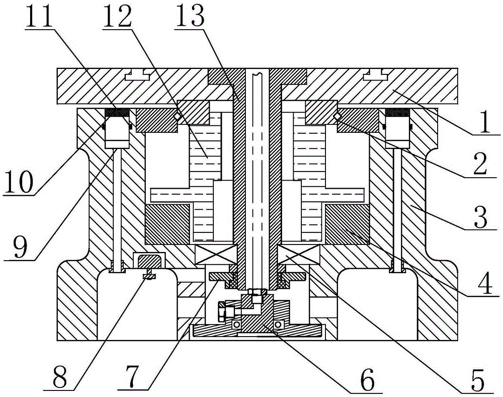
[0013] The specific implementation manner of the present invention will be described in detail below in conjunction with the accompanying drawings.

[0014] Such as figure 1 The rotary workbench shown includes a worktable 1, a motor stator 4, a rotor 12, a cross roller slewing bearing 2, a deep groove ball bearing 5 and a machine base 3, and a centering shaft 13 is fixed in the center of the worktable 1 , the rotor 12 is fixed in the middle of the outer wall of the centering shaft 13, the upper end of the rotor 12 is provided with a notch, and the rotor 12 is fixed to the bottom and the inner wall of the inner ring of the cross roller slewing bearing 2 through the notch, The worktable 1 is fixed to the top of the inner ring of the cross roller slewing bearing 2, the outer ring of the cross roller slewing bearing 2 is fixed to the upper part of the machine base 3, and the motor stator 4 is fixed to the machine base 3, the outer ring of the deep groove ball bearing 5 is fixed t...


PUM


Abstract

The invention relates to a rotary working table. The rotary working table comprises a working surface, a motor stator, a rotor, a crossed roller swing bearing, a deep groove ball bearing and a table base, wherein a spigot shaft is fixed in the center of the working surface; the rotor is fixed in the middle of the outer wall of the spigot shaft; the crossed roller swing bearing is arranged among the working surface, the rotor and the table base; the motor stator is fixed in the middle of the inner wall of the table base; the outer ring of the deep groove ball bearing is fixed with the lower part of the inner wall of the table base; the inner ring of the deep groove ball bearing is fixed with the lower part of the spigot shaft; a synchronous pulley is further fixed in the position, below the inner ring of the deep groove ball bearing, of the spigot shaft; an encoder feedback detection device is fixed in the position, corresponding to the synchronous pulley, of the lower part of the table base; cylinder locking levers are arranged in the side wall of the table base, and a friction brake pad is fixed at the top of each cylinder locking lever. The rotary working table is high in support precision and high in rigidity, realizes mechanical and electrical integration and avoids mechanical transmission errors.

Description

technical field [0001] The invention relates to a rotary worktable. Background technique [0002] The rotary table is the core component of various machine tools such as vertical lathes, milling machines, machining centers, and CNC gear shaping machines. The movement accuracy, bearing capacity, and ability to deal with impacts of the rotary table are related to the production and processing of the entire machine tool. Capacity and efficiency. In order to improve the accuracy, the existing rotary table usually uses the servo drive mechanism and the speed reduction device to drive the rotary table to rotate. However, due to the large size and complex structure of the rotary table in this way, the overall load-carrying capacity is affected. , which in turn affects the stability, and it is inconvenient to maintain later, and although this type of rotary table is more accurate than other rotary tables, it still cannot meet the high-precision machining requirements. Contents of ...

Claims


Application Information

Patent Timeline
IPC IPC(8): B23Q1/26
CPCB23Q1/26
Inventor 高尔荣谭广
Owner 浙江博雷重型机床制造有限公司
Why Eureka
Try Eureka