Pneumatically-balanced automatic brake device combined with calliper brake

A pneumatic balance and clamp technology, which is applied in the direction of manufacturing tools, large fixed members, metal processing machinery parts, etc., can solve the problems of not having automatic brake devices, etc., and achieve the effect of improving safety and controllability and improving quality

Inactive Publication Date: 2016-02-24
SHANDONG WEIDA HEAVY INDS
View PDF7 Cites 5 Cited by
  • Summary
  • Abstract
  • Description
  • Claims
  • Application Information

AI Technical Summary

Problems solved by technology

However, the structure of the linear motor itself does not have an automatic brake device. When the power is suddenly lost, an additional device is required to realize the brake

Method used


Image

  • Pneumatically-balanced automatic brake device combined with calliper brake

Examples


Embodiment Construction

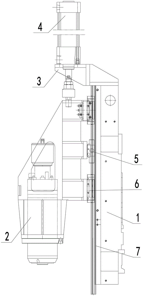
[0016] The present invention will be further described below in conjunction with accompanying drawing and specific embodiment:

[0017] The invention as figure 1 As shown, the pneumatic balance combined clamper automatic brake device includes clamper 5, clamper 5 is fixed on the spindle box 2 of the CNC machine tool, and the wire gauge slide plate 6 is also fixed on the machine tool spindle box 2. The clamper 5 and the wire gauge slide plate 6 is installed on the wire gauge, the wire gauge 7 is installed on the slide plate 1, and the wire gauge slide plate 6 is arranged in two groups at the upper and lower positions of the clamp 5 respectively. The upper end of the slide plate 1 is provided with a balance cylinder support 3 which is installed on the slide plate 1, and a balance cylinder 4 is established on the balance cylinder support 3, and the piston end of the balance cylinder 4 is connected to the machine headstock 2.

[0018] The balance cylinder support 3 protrudes from...


PUM


Abstract

The invention relates to a pneumatically-balanced automatic brake device combined with a calliper brake, which is applied to a vertical moving component of a numerically-controlled machine tool. The technical scheme adopted in the invention is as follows: the pneumatically-balanced automatic brake device combined with the calliper brake comprises the calliper brake, wherein the calliper brake and a wire gauge slide plate are fixed on a machine tool spindle box, the calliper brake and the wire gauge slide plate are installed on a wire gauge, and the wire gauge is fixed on a slide plate; a balance cylinder support is arranged on the upper end part of the slide plate and installed on the slide plate, a balance cylinder is arranged on the balance cylinder support, and a piston end of the balance cylinder is connected with the machine tool spindle box. The pneumatically-balanced automatic brake device combined with the calliper brake, which is disclosed by the invention, has the following advantages and effects: due to the structure, a displacement of the vertical moving component of the numerically-controlled machine tool with a linear motor due to dead weight and inertia in case of sudden power loss can be avoided; the machining accuracy of the machine tool is improved (vibration is prevented), and in particular, brake can be carried out in an emergency, so that the safety and the controllability of the machine tool are improved; and moreover, the quality for machining components can be better improved.

Description

technical field [0001] The invention relates to an automatic brake device of a pneumatic balance combined clamp, which is applied to a vertically moving part of a numerically controlled machine tool. Background technique [0002] In recent years, with the rapid development of automatic control technology and microcomputers, higher requirements have been placed on the positioning accuracy of various automatic control systems. In this case, the traditional rotating motor plus a set of transformation mechanisms Linear motion drive devices are far from meeting the requirements of modern control systems. For this reason, many countries in the world are researching, developing and applying linear motors in recent years, making the application fields of linear motors more and more extensive. [0003] During the actual use and processing of ordinary CNC machine tools, when the CNC machine tool suddenly loses power, the vertical moving parts will automatically lock under the action o...

Claims


Application Information

Patent Timeline
Patent Type & Authority Applications(China)
IPC IPC(8): B23Q11/00B23B19/00B23Q5/58
CPCB23Q11/0092B23Q1/70B23Q5/58B23Q11/00
Inventor 苗付标孔德斌孔令涛吕高见许慎杰张中秋明满意王坤
Owner SHANDONG WEIDA HEAVY INDS
Why Eureka
Try Eureka