Automatic detecting system for saw blade

An automatic detection and saw blade technology, which is applied in the directions of automatic packaging control, packaging, packaging protection, etc., can solve the problems of subjectivity in judgment, high labor intensity of workers, and low degree of automation, so as to improve work efficiency, high work efficiency, and automation high degree of effect

Inactive Publication Date: 2016-02-24
DONGGUAN XINTENG ROBOT TECH
View PDF7 Cites 15 Cited by
  • Summary
  • Abstract
  • Description
  • Claims
  • Application Information

AI Technical Summary

Problems solved by technology

[0003] The detection of saw blades in the prior art is generally realized by manual observation with the naked eye. On the one hand, long-term visual observation of workers is likely to cause vis

Method used


Image

  • Automatic detecting system for saw blade
  • Automatic detecting system for saw blade
  • Automatic detecting system for saw blade

Examples


specific Embodiment 1

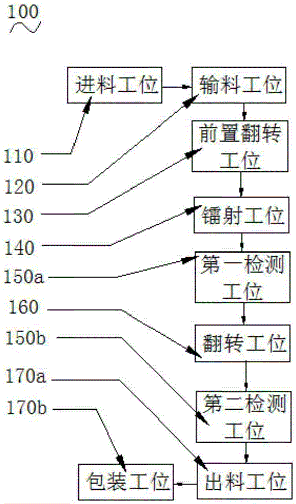
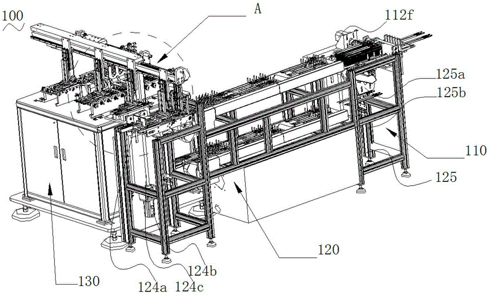
[0047] Such as figure 1 , image 3 , Figure 4 with Figure 5 As shown, are respectively the structural schematic diagram of the specific embodiment 1, two partial perspective views and partial enlarged views.

[0048] This embodiment is for the detection of blue saw blades. The saw blade automatic detection system 100 includes a feeding station 110, a feeding station 120, a front flipping station 130, a laser station 140, and a first detection station 150a connected in sequence. , the turning station 160, the second detection station 150b, the discharging station 170a, the packaging station 170b and the transfer assembly 180 used for transferring saw blades between adjacent stations.

[0049] Such as Image 6 with Figure 7 Shown are respectively a perspective view and a front view of the feeding station of the present invention.

[0050] The feeding station 110, the feeding station 110 includes a feeding tray 111 for placing the saw blade, a first positioning assembly ...

specific Embodiment 2

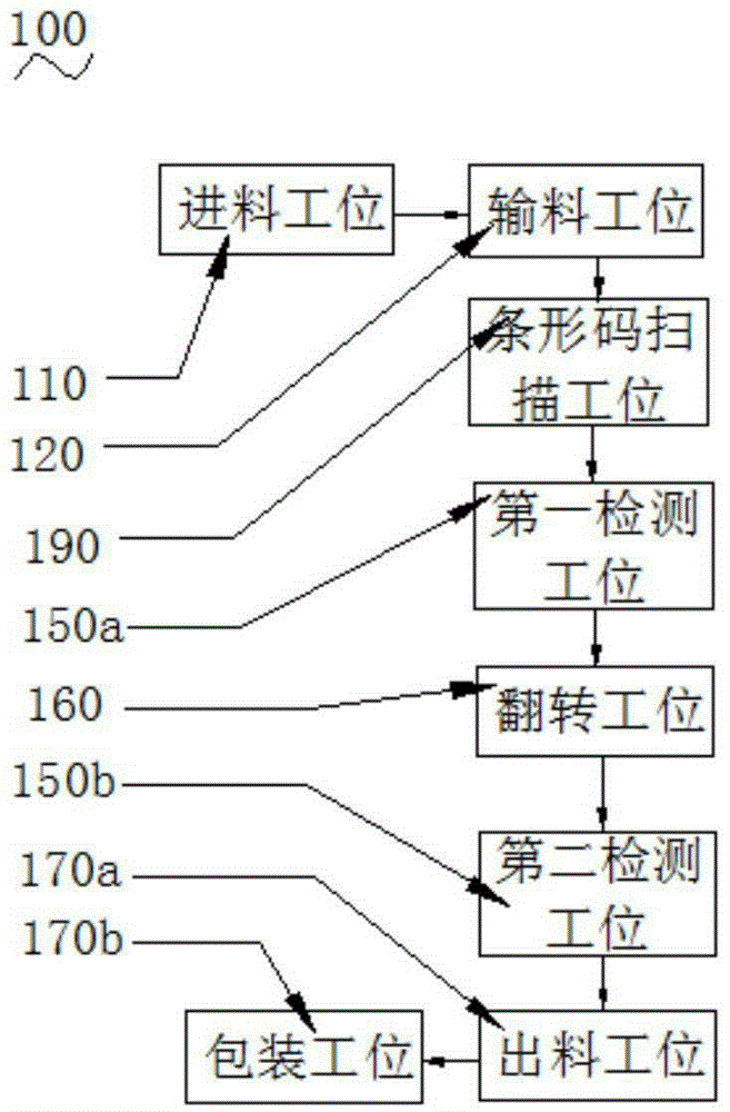
[0075] Such as figure 2 Shown, is the structural representation of specific embodiment 2, and the difference with above-mentioned embodiment 1 is:

[0076] This embodiment is for the detection of white saw blades. The saw blade automatic detection system 100 includes a feeding station 110, a feeding station 120, a barcode scanning station 190, a first detection station 150a, a turning station 160, a first Two detection station 150b, discharge station 170a, packaging station 170b and transfer assembly 180 for saw blade transfer between adjacent stations.

[0077] The feeding station 110, the feeding station 110 includes a feeding tray 111 for placing the saw blade, a first positioning assembly 112 positioned in front of the feeding tray 111 for positioning the saw blade left and right, and a feeding tray 112 for transporting the saw blade. The conveyor belt 113 of the feed tray 111, the feeding drive assembly 114 for driving the movement of the conveyor belt 113, the feed tra...


PUM


Abstract

The invention relates to the field of saw blade detecting, in particular to an automatic detecting system for a saw blade. The automatic detecting system for the saw blade comprises a material feeding workstation. The material feeding workstation comprises a material feeding plate, a first positioning assembly, a conveyor belt and a material feeding driving assembly, wherein the material feeding plate is used for placing the saw blade, the first positioning assembly is located in front of the material feeding plate and is used for conducting left-and-right positioning on the saw blade, the conveyor belt is used for conveying the material feeding plate with the saw blade placed, and the material feeding driving assembly is used for driving the conveyor belt to move. A counter is arranged on the material feeding plate. The first positioning assembly comprises a material receiving frame, a plurality of first positioning blocks, material grooves, an upper pressing roller, a lower pressing roller and a positioning driving assembly, wherein the multiple first positioning blocks are all arranged on the material receiving frame, the material grooves are formed between the two adjacent first positioning blocks and are used for placing the saw blade, the upper pressing roller and the lower pressing roller are used for pressing the saw blade to enable the saw blade to be disengaged from a fixture and are both located at the output end of the material receiving frame, and the positioning driving assembly is used for driving the upper pressing roller and the lower pressing roller to move relatively. The upper pressing roller is located above the lower pressing roller, and a gap matched with the thickness of the saw blade is reserved between the upper pressing roller and the lower pressing roller. The automatic detecting system for the saw blade is high in automation degree, high in working efficiency, high in detecting precision and wide in application range.

Description

technical field [0001] The invention relates to the field of saw blade detection, in particular to an automatic detection system for saw blades. Background technique [0002] After the saw blade is produced and the surface printing is completed, a series of follow-up processing is required, such as checking whether the front and back sides of the saw blade are qualified for printing, packaging the saw blade that passes the inspection on both sides, and checking whether there is a barcode on the surface of the white saw blade , for the blue saw blade, it is also necessary to engrave icons etc. on the reverse side. [0003] The detection of saw blades in the prior art is generally realized by manual observation with the naked eye. On the one hand, long-term visual observation of workers is likely to cause visual fatigue and judgment is subjective, resulting in large errors and low detection accuracy. Second, the labor intensity of workers is high, The degree of automation is ...

Claims


Application Information

Patent Timeline
IPC IPC(8): B65B35/44B65G47/248B65B57/00B07C5/00
CPCB07C5/00B65B35/44B65B57/00B65G47/248
Inventor 韩文召房豪欧阳于超陈炼
Owner DONGGUAN XINTENG ROBOT TECH
Why Eureka
Try Eureka