Underground optical fiber vortex-shedding flowmeter and underground flow measuring method

A vortex flowmeter and optical fiber technology, applied in the field of optical fiber vortex flowmeter and flow measurement, downhole optical fiber vortex flowmeter and downhole flow measurement, can solve the problems of low measurement accuracy, unusable, poor stability, etc., and achieve improvement The effect of sensitivity, accurate measurement

Inactive Publication Date: 2016-02-24
HARBIN INST OF TECH
View PDF9 Cites 4 Cited by
  • Summary
  • Abstract
  • Description
  • Claims
  • Application Information

AI Technical Summary

Problems solved by technology

[0005] The present invention aims to solve the problem of low measurement accuracy and poor stability caused by the influence of the optical fiber being corroded by the fluid and the influence of the measuring element on the flow field and flow in the pipeline in the existing optical fiber flowmeter, as well as the complex structure of the existing flowmeter. Problems that cannot be used in highly corrosive environments, and then propose a downhole optical fiber vortex flowmeter and downhole flow measurement method

Method used


Image

  • Underground optical fiber vortex-shedding flowmeter and underground flow measuring method
  • Underground optical fiber vortex-shedding flowmeter and underground flow measuring method
  • Underground optical fiber vortex-shedding flowmeter and underground flow measuring method

Examples


specific Embodiment approach 1

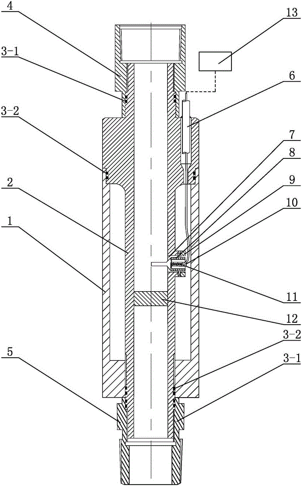
[0028] Specific implementation mode one: combine figure 1 Describe this embodiment, a downhole fiber optic vortex flowmeter described in this embodiment includes a fiber grating demodulator 13, and this embodiment also includes a housing 1, a central tube 2, an upper joint 4, a lower joint 5, and an armored optical cable 6. The probe 8, the pressure plate 9, the central axis 10, the fiber grating 11 and the vortex generator 12, the upper joint 4, the central tube 2, and the lower joint 5 are connected sequentially from top to bottom, and the shell 1 is set on the outer wall of the central tube 2 Above, the vortex generator 12 is arranged in the center tube 2, and the middle part of the outer wall of the center tube 2 has a through hole 7, the probe 8 is installed in the through hole 7 through the pressure plate 9, and the neutral axis 10 is inserted in the probe 8, The fiber grating 11 is arranged in the neutral axis 10 , one end of the armored optical cable 6 is connected to ...

specific Embodiment approach 2

[0029] Specific implementation mode two: combination figure 1 Describe this embodiment. The downhole fiber optic vortex flowmeter described in this embodiment also includes two first sealing rings 3-1 and two second sealing rings 3-2. Two first sealing rings 3-1 are provided, and two second sealing rings 3-2 are provided at the connection between the lower joint 5 and the lower end of the housing 1 . Other components and connections are the same as those in the first embodiment.

specific Embodiment approach 3

[0030] Specific implementation mode three: combination figure 1 To illustrate this embodiment, the cross-section of the vortex generator 12 of a downhole fiber optic vortex flowmeter in this embodiment is a polygon with three corners removed from an isosceles triangle, and the vortex generator 12 is made of 316L stainless steel.

[0031] In this embodiment, the bottom surface of the triangular column of the vortex street generating body 12 is the upstream surface, and the vertical bisector of the upstream surface is in the same plane as the flat part of the probe. The vortex street generating body 12 plays the role of generating and separating the vortex, and the triangular column structure The vortex signal generated by the vortex generator 12 is both strong and stable, and can also reduce other disturbances and noises of the fluid. Other compositions and connections are the same as those in Embodiment 1 or 2.


PUM


Abstract

The present invention discloses an underground optical fiber vortex-shedding flowmeter and an underground flow measuring method, and aims to solve the problems, of low measuring precision and poor stability, caused by situations that optical fibers are influenced by fluid corrosion and that measuring elements influence a flow field and flow inside a pipeline in a conventional flowmeter, and the problem that the conventional optical fiber flowmeter is complex in structure and cannot be used in high-temperature, high-voltage and high-erosion environments. An upper joint, a central tube and a lower joint are connected from top to bottom in turn, a housing sleeves an outer side wall of the central tube, a vortex shedder is arranged inside the central tube, a through hole is formed in the middle part of the outer side wall of the central tube, a probe is installed inside the through hole through a pressing plate, a central shaft is inserted inside the probe, a fiber bragg grating is arranged inside the central shaft, and one end of an armored cable is connected with the fiber bragg grating while the other end of the armored cable is connected with a fiber bragg grating demodulation instrument. The underground optical fiber vortex-shedding flowmeter is applied to the oil field equipment field.

Description

technical field [0001] The invention relates to an optical fiber vortex flowmeter and a flow measurement method, in particular to an optical fiber vortex flowmeter and a downhole flow measurement method, belonging to the field of oil field equipment. Background technique [0002] Flow rate is an extremely important parameter in the process of oil production. In daily oil recovery work, the accuracy and reliability of flow measurement is related to the oil field production, which is of great significance to improve the development effect of oil and water wells in oil fields. In the process of oil extraction, the real-time measurement of crude oil flow is particularly difficult due to the special environmental conditions downhole and the special flow state of crude oil. In addition, the measurement of downhole flow involves liquid, gas and multiphase fluid, and the measurement of polymer flow should also take into account the viscous effect of high-viscosity non-Newtonian flui...

Claims


Application Information

Patent Timeline
Patent Type & Authority Applications(China)
IPC IPC(8): G01F1/32
CPCG01F1/32
Inventor 张洪涛张广玉王振龙宋文平李隆球刘丽丽
Owner HARBIN INST OF TECH
Why Eureka
Try Eureka