PMMA light guide plate with double-sided dotted microstructures

A microstructure and light guide plate technology, applied in the field of optical components, can solve problems such as unqualified processing, affecting product quality, and difficult processing, so as to ensure reflectivity and scattering rate, improve space utilization, and improve light guide uniformity Effect

Inactive Publication Date: 2016-02-24
CHONGQING LINGCHUANGFU PHOTOELECTRIC TECH
View PDF10 Cites 2 Cited by
  • Summary
  • Abstract
  • Description
  • Claims
  • Application Information

AI Technical Summary

Problems solved by technology

The cross-section of the dots on the dot surface of the traditional light guide plate is mostly a U-shaped groove or a V-shaped groove, and its light-emitting surface is a mirror surface. The engraving process is used for production, the production efficiency is low and the cost is high; on the other hand, the reflection and refraction effect of the U-shaped groove is not as good as that of the V-shaped groove, and the bottom of the V-shaped groove is a tapered structure, which is difficult to

Method used


Image

  • PMMA light guide plate with double-sided dotted microstructures
  • PMMA light guide plate with double-sided dotted microstructures
  • PMMA light guide plate with double-sided dotted microstructures

Examples


Embodiment Construction

[0022] The technical solutions in the present invention will be further described below in conjunction with the accompanying drawings and embodiments.

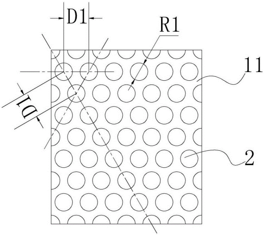
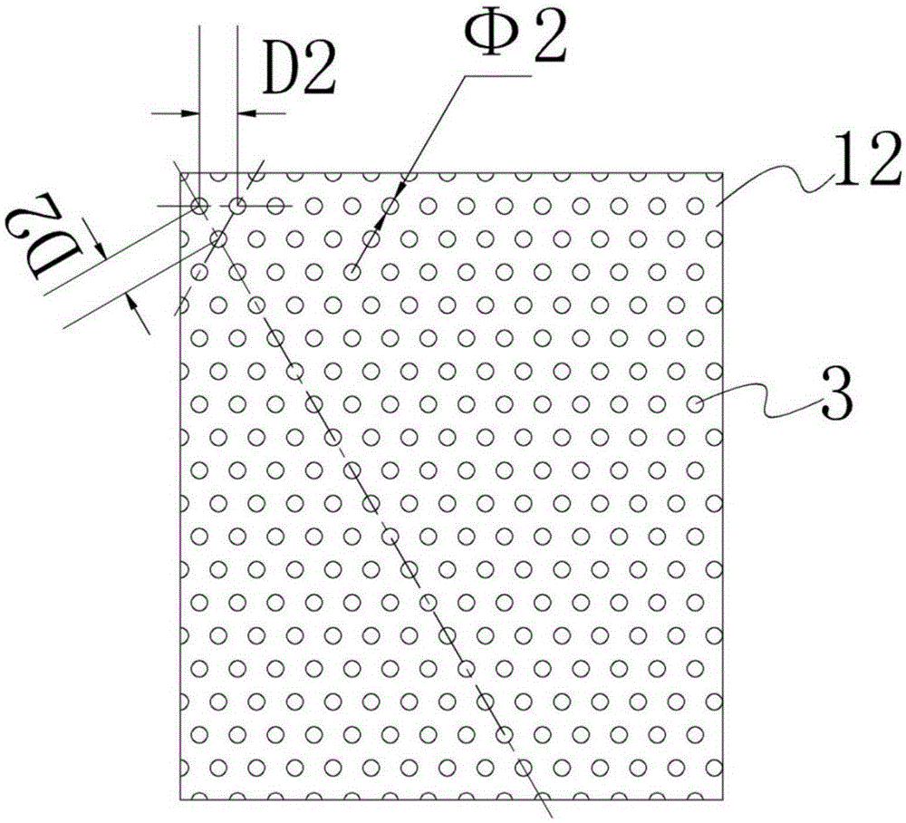
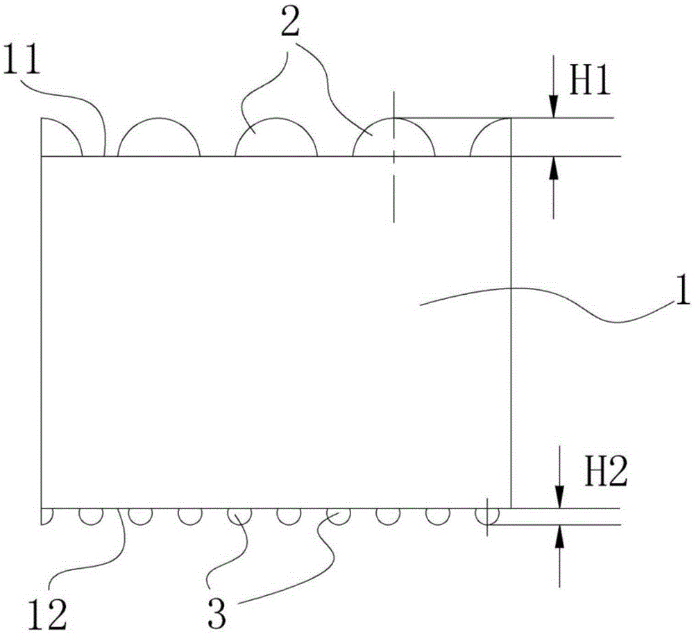
[0023] like Figure 1-Figure 3 As shown, the present invention includes a transparent plate body 1 made of PMMA, and the transparent plate body 1 has a light-emitting surface 12 for emitting light and a reflective surface 11 opposite to the light-emitting surface 12;

[0024] like figure 1 and image 3 As shown, the reflective surface 11 is provided with a plurality of reflective protrusions 2 in a spherical crown and arranged in a quincunx shape. This quincunx distribution is more uniform than the traditional row and column distribution, which improves the space utilization of the reflective surface 11 and improves The reflectivity of the light on the reflective surface 11 is improved; the reflective protrusion is made of PMMA material and integrally formed with the transparent plate body 1, thereby avoiding the reflection ...


PUM

PropertyMeasurementUnit
Bottom diameteraaaaaaaaaa
Heightaaaaaaaaaa
Center distanceaaaaaaaaaa

Abstract

The invention discloses a PMMA light guide plate with double-sided dotted microstructures. The PMMA light guide plate comprises a transparent plate body made of PMMA material. The transparent plate body is provided with a light emergent surface used for light emergence and a reflecting surface opposite to the light emergent surface. The reflecting surface is provided with multiple reflecting bulges which are identical in dimension. The light emergent surface is provided with multiple scattering bulges which are identical in dimension. The reflecting bulges and the scattering bulges are spherical-crown-shaped and arranged in the shape of plum blossoms, and are made of the PMMA material and integrated with the transparent plate body. The basal diameter and the height of the scattering bulges are respectively less than the basal diameter and the height of the reflecting bulges. Light conversion rate can be 80% or more without light guide particles so that conventional laser engraving process production is changed and production cost is reduced; the scattering bulges further scatter the light rays of the light emergent surface and emergent light uniformity can be 85% or more; the scattering bulges and the reflecting bulges and the transparent plate body are made of the same material and are integrated so that loss of the light rays can be avoided; and the scattering bulges and the reflecting bulges are arranged in the shape of plum blossoms so that space utilization rate can be enhanced and reflectivity and scattering rate can be guaranteed.

Description

technical field [0001] The invention relates to the field of optical elements, in particular to a PMMA light guide plate with double-sided point-shaped microstructure. Background technique [0002] The term light guide plate comes from English LightGuide, which originated from the application of liquid crystal display (LCD). LCD displays the brightness of the display screen through the backlight module, and the light guide plate is an important role in the backlight module. Light guide plates are mostly used in LCD monitors, notebook computers, LCD TVs, mobile phones and various electronic products, including office equipment such as fax machines and copiers, calculators, learning instruments, digital cameras, medical film viewers, watches, electronics, etc. . [0003] The main function of the light guide plate is to direct the incident light from the backlight to the LCD liquid crystal display to show the brightness of the backlight and the display, and at the same time ha...

Claims


Application Information

Patent Timeline
IPC IPC(8): G02B6/00G02F1/13357
CPCG02B6/0036G02F1/133606
Inventor 郭志强程媛媛
Owner CHONGQING LINGCHUANGFU PHOTOELECTRIC TECH
Why Eureka
Try Eureka